
- Why Switchgear Testing is done?
- What is done during Switchgear Testing?
- Operations Carried Out in Switch Gear Testing
- Switchgear Test Procedures
- Visual and Mechanical Inspection
- Switchgear Routine Test
- Frequency Voltage Withstand Test
- Over-Potential Tests (Hi-Pot Test)
- Insulation Resistance Test
- Mechanical Operating Test
- Voltage Withstand Tests for Control & Auxiliary Circuits
- Sequence Test
- Electrical Operation Test
- Contact Resistance Test
- Partial Discharge Test
- Artificial Pollution Test
- Dielectric Test
- Switching Impulse Voltage Test
- How often should Switchgear be tested?
- Why is Switchgear Testing Important?
- Advantages of Switchgear Testing
Switchgear testing must be done semi-annually, with a visual and infrared check done once a year. More frequent testing may be required due to equipment difficulties or deterioration, manufacturer faults (or) high reliability requirements.
Due to this, switchgear must protect the power system and keep workers as well as additional equipment safe in the occurrence of a panel breakdown.
In order to handle as many real-life circumstances as possible, switchgear must be tested in normal and abnormal conditions. National & international standards specify the parameters for these tests. The manufacturer tests all parameters throughout equipment development to ensure long-term performance.
It’s difficult to determine all utility and customer needs at one place. They can now choose between IEC 62271-100 and IEC 62271-200 equipment for different voltage levels and standards.
Why Switchgear Testing is done?
Short circuits caused by component failures can damage products, endanger lives, and ruin business reputation. Switchgear & electrical wiring fittings must be tested for safety and compliance with international standards.
Electrical asset management requires regular switchgear inspection and testing. It can extend equipment life, avoid unplanned outages, and improve safety. It boosts predictability, reliability, and maintenance savings.
What is done during Switchgear Testing?
We do electrical (high voltage, insulation resistance, short-circuit), temperature-rise, mechanical strength, endurance, and environmental tests.
We test voltage switchboards/tap-off boards, busbar trunking systems, distribution boards/consumer units, isolating switches/disconnectors, low-voltage fuses, circuit breakers (MCB/RCCB/RCBO), steel surface cable, trunking, fire alarm panels, etc.

Operations Carried Out in Switch Gear Testing
- Inspect the alignment, grounding, and connections.
- Clean impurities from all sections of the Switch Gear.
- Inspect electrical & mechanical components for evidence of dampness or rust.
- Inspect current & voltage ratings to confirm they are in compliance with the manufacturer’s specifications.
- Check electrical connections for high resistance.
- Conduct impulse and cycle tests to make sure that all circuit breakers & fuses are performing efficiently.
- Insulation Resistance Testing
- Ground resistance tests
- Emergency response for switch gear faults
- Technical instruction for using and handling switchgear.
Switchgear Test Procedures
Switchgear tests must be suitable for the unit’s voltage levels. According to the test results, a typical switchgear evaluation can become a maintenance procedure. With the appropriate actions, you may maintain everybody in the facility on board & complete all of your mandatory tests.
There are three stages in coordinating a power failure for switchgear testing:
Before: Gather all required materials & review the equipment’s history. Inform your employees about the times you will be testing. To streamline the process, develop a particular work plan and testing timetable.
During: Disconnect as needed and follow safety precautions. Perform inspections and cleanings. Test and replace necessary components. Before restarting the unit, conduct a physical examination and double-check every work.
After: Discuss any concerns that staff may encounter. Create a report outlining the testing results & necessary next steps.
Your switchgear testing procedures can have a substantial impact on the longevity of your electrical system and as follows:
- Visual and Mechanical Inspection
- Switchgear Routine Test
- Frequency Voltage Withstand Test
- Over-Potential Tests (Hi-Pot Test)
- Insulation Resistance Test
- Mechanical Operating Test
- Voltage Withstand Tests for Control & Auxiliary Circuits
- Sequence Test
- Electrical Operation Test
- Contact Resistance Test
- Partial Discharge Test
- Artificial Pollution Test
- Dielectric Test
- Switching Impulse Voltage Test
Visual and Mechanical Inspection
- Inspect the switchgear and other components for physical damage or faults.
- Check the nameplate information to ensure that it is correct.
- Inspect enclosures for appropriate alignment, foundation repair, grounding, and vermin entry.
- Inspect all covers, panels, and doors for painting and good fit.
- Examine whether all of the transportation locks are disconnected.
- Check for smooth and proper movement of rails & guides, racking systems, shutters, and rollers.
- Check that the primary & secondary contacts are properly aligned.
- Check the operation of any mechanical interlocks.
- Check the tightness for every bolted connections.
- Check for the correct phasing connection of the bus bar.
- Perform a mechanical and visual inspection of the breaker/contractor in accordance with the section.
- Perform a mechanical and visual inspection of instrument transformers as specified in the section.
- Perform a mechanical and visual inspection of all disconnect/grounding switches as specified in the section.
Switchgear Routine Test
The IEC62271-100 standard specifies many necessary routine tests. This is one of standards that should be utilized as a reference when conducting tests. The ISO9001 standard assures that the manufacturer’s switchgear devices work consistently.
The reliability of the power system can only be maintained if a routine maintenance schedule is established and followed on a regular basis.
Circuit breakers that failed to trip properly during a fault can result in fires, equipment damage, and increased arc flash hazards for workers executing electrical maintenance (or) operations.
Certain extra tests (or) inspections can be required & specified by the manufacturer to ensure that the item functions properly in service and meets the stated ratings.

Frequency Voltage Withstand Test
The frequency voltage withstand test must employ the same technique, measurement value, and duration as the frequency type test.
Ex: 12 kV rated switchgear must be tested phase-by-phase & each phase to earth at 28 kV for 1 minute.
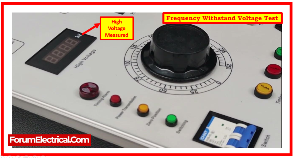
Before conducting the tests, voltage transformers and surge suppressors should be isolated (or) disconnected from the primary circuits.
Over-Potential Tests (Hi-Pot Test)
Over-potential tests on a breaker are comparable to insulation resistance tests.
These tests are far more likely to be utilized with medium & high voltage breakers.
A common over-potential critical test checks vacuum circuit breaker bottles to ensure their integrity. This test involves placing a high voltage across a bottle’s opening to ensure its integrity.
Without conducting this test, we would not be able to determine if the bottle yet has a vacuum.
It is essential to remember that some breaker manufacturers require the usage of an AC Hi-Pot test.
During the test, be conscious that an arc within the container can generate X-Ray radiation. To ensure safety throughout this test, we must stand at least 3 feet away from the bottle and keep metal between themselves & it. Despite the low risk of radiation exposure, awareness is essential.
Insulation Resistance Test
In insulation resistance tests, temperature data must be taken in order to apply temperature corrections.
During the testing, it is essential that we provide the correct voltage to insulation, with the voltage level determined by the equipment’s voltage class.
We take several insulation readings, including the initial at 30 seconds & the second at one minute. If we take a 10-minute reading from a winding, we are going to divide it by a 1-minute reading. This will provide us the Polarisation Index.
The next step is to determine the Dielectric Absorption Ratio that is the 1-minute value divided by the 30-second reading.
If we have access to a 10-minute reading, we’ll divide it by the 1-minute reading to get the Polarisation Index.
Once all readings & calculations are finished, we may use our results to accurately grade the insulation.
Mechanical Operating Test
Evaluating the mechanical operation of circuit breakers is important; the mechanical operating time needs to be documented and compared to type test values.
Not only is the mechanical operating time evaluated, but also the variances in running times at the minimum, nominal, & maximum operating voltages to ensure that the correct trip and closure coils are installed.
By measuring the time it takes for the switchgear to charge, the test will also verify that the proper mechanism charging motor (or) solenoid is installed.
Voltage Withstand Tests for Control & Auxiliary Circuits
Voltage withstand tests employ a 2 kV voltage to assess the earth on secondary wiring. During these testing, electronic equipment may have to be disconnected.
The resistance of each phase’s primary circuit should be measured with specialized equipment and compared to the type test values and design acceptance criteria.
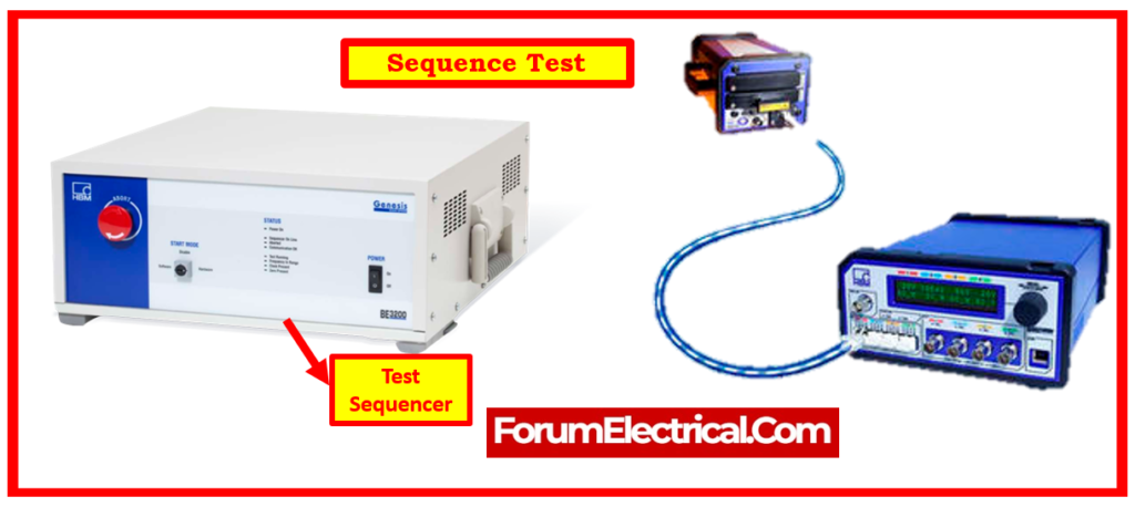
Sequence Test
Electrical Operation Test
According to IEC 60439, 8.3.1, electrical operation tests for equipment set up in switchgear & MCC (Ex: circuit breakers, magnetic contactors, switches, & relays) must be performed simultaneously by providing a combination of simulated input and output circuits, and the operation must be verified as normal.
Contact Resistance Test
- If contacts are not maintained on a regular basis, resistance builds up as a result of frequent arcing, reducing the contacts’ ability to transport current. This test measures the quality of mating between the contact surfaces & pivot points. Contact resistance must be kept as minimal as possible to minimize localized heating & power loss.
- This test confirms that the busbar joints are properly linked and tightened.
- The test must be performed with CBs inserted & closed.
- Compute the contact DC resistance between panels using a 100 Ampere DC. This will include the CB contact resistance, busbar joint, CB cluster resistance, & CT primary resistance (if applicable).
- The results should be consistent throughout all phases and measurement sets.
- Other affecting parameters to consider include the length of the measured track, busbar rating, CB and CT, and temperature.
Partial Discharge Test
Partial discharge testing is a component test that should not be performed on whole switchgear, when the design consists of a mixture of conventional components (e.g., CTs and VTs) that may be tested in compliance with the appropriate standards.
However, this test is advised for switchgear that uses organic insulating materials, such as integrated switchgear design, particularly GIS, where live parts & connections are encased in solid insulation.
Artificial Pollution Test
These tests are only applicable to outside installations and are conducted in accordance with an agreement among the user & the manufacturer. The wait times for the above tests are established in standards against the system’s wait time.
Dielectric Test
The power system occasionally faces transient power frequency overvoltages caused by load throw, incorrect transformer OLTC operation, resonance, insufficient shunt compensation, and so on.
Dielectric tests are performed to check the rated insulating strength of the switchgear, ensuring that when a circuit breaker is placed into service, its design can survive overvoltages caused by all of the above as well as lightning, switching operations, and so on.
This is validated in accordance with the standards.
Switching Impulse Voltage Test
This test is not required (optional). It tests if the switchgear can withstand overvoltages caused by switching surges. This test has significance for system voltages higher than 300 kV.
Switching surges occur when unloaded EHV or lines are opened and closed, causing inductive or capacitive loads to fail.
Switching surges have a longer duration (2500 µs), slower rate of rise, and are represented by a conventional switching impulse test wave of 250/2500 μs.
How often should Switchgear be tested?
Switchgear must be tested on an annual basis. Consistent testing & preventative maintenance are essential for the longevity and effectiveness of your switchgear system. Along with routine insulation & mechanical testing, you must perform visual inspections to look for part discoloration (or) accumulation of debris. Early resolution of these small faults can also help to ensure optimal switchgear performance.
Addressing physical damage & poor test results immediately will allow you to keep your system functioning smoothly and efficiently. Every year, personally test and inspect switchgear elements like the following:
- Circuit breakers
- Switches
- Wiring, Insulation, and Disconnect Points
- Mounting bolt tightness
- Termination tightness
- Temperature control panels
- Thermostats
Why is Switchgear Testing Important?
Minor problems might quickly escalate into major repairs if they are not addressed on an ongoing basis. Rust, corrosion, & stripped insulation are simple to detect and repair during maintenance checks.
Test and maintain switchgear on a regular basis.
Prevent failures: Running the equipment till failure implies only replacing parts when the failure light illuminates. Routine testing helps you eliminate potential faults and extend the usable life of your components.
Save money: Maintenance on a routine basis can help you avoid paying for expensive emergency repairs.
Improve function: Having properly functioning & tested equipment will boost the overall output of the electrical system by making sure it is operating at peak efficiency.
Advantages of Switchgear Testing
- Meeting regulatory rules and standards can help to reduce the company’s risks.
- Improve the quality & safety of your products & procedures.
- Save time and money.
- Increase client trust in your goods by conducting independent testing.
- Partnering with a regulatory requirements & standards expert can help you reduce time to market and expand market access.