
- What is a Transmission Tower?
- Parts of a transmission tower
- Electrical Transmission Tower Types
- Special Type Tower
- High Voltage Alternating Current transmission lines
- High-voltage direct current (HVDC) transmission lines
- Single-phase alternating current railway traction lines
- Design of Transmission Towers
- Tower height Selection
- Frequently Asked Questions:
What is a Transmission Tower?
A transmission tower is a tall structure (usually a steel lattice tower) that holds up an overhead power line. It is also called a
- Power transmission tower,
- Power tower, or
- Electricity pylon.
In electrical grids, they hold high-voltage transmission lines that move large amounts of electricity from power plants to substations. Utility poles hold lower-voltage sub-transmission & distribution lines that move electricity from sub-stations to electric customers.
Transmission towers must hold the heavy transmission conductors high enough off the ground to be safe. Also, all towers have to be able to stand up to all types of natural disasters.
So, designing transmission towers is an important engineering work that utilises concepts from civil engineering, mechanical engineering, and electrical engineering simultaneously.
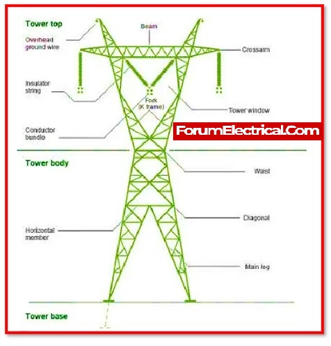
Parts of a transmission tower
A key component of a power transmission system is a power transmission tower. There are the following components that constitute a power transmission tower:
- Peak of a transmission tower
- Cross arm of a transmission tower
- Boom of a transmission tower
- Cage of a transmission tower
- Transmission Tower-Body
- Leg of a transmission tower
- Stub (or) Anchor Bolt and Base plate assembly of a transmission tower.
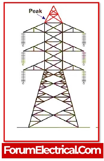
1). Peak of a transmission tower
The part of the transmission tower that is located just above the top cross arm is referred to as the peak. Typically, an earth shield wire is linked to the very tip of this height.
2). Cross arm of a transmission tower
The transmission conductor is held in place by the cross arms of the transmission tower. The dimensions of the cross arm can vary depending on,
- Level of voltage used for transmission,
- Configuration and
- Minimum forming angle for tension (stress) distribution.

3). Boom of a transmission tower
The boom is a portion of a tower that has a horizontal arrangement and takes the form of a rectangular beam with a cross-section that tapers towards the terminal section.
In most applications, the boom will be attached to the lower body in order to provide mechanical support to the power conductors.
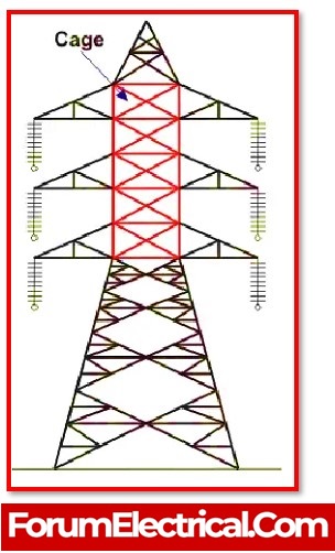
4). Cage of a transmission tower
The part of a transmission tower that is known as the cage is located between the tower body and the peak. The cross arms are located inside this section of the tower.
Depending on the height (tower elevation) of the tower, the form of the enclosure might either be a square or a triangle.
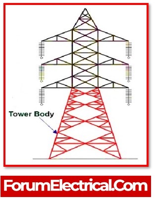
5). Transmission Tower-Body
During the design process of a transmission tower, the following considerations must be observed:
- The minimal level of ground clearance required at the point on the conductor that is lowest above ground level.
- The number of inches that the insulator string occupies (length).
- The minimal clearance that should exist between each set of conductors as well as between each set of conductors and the tower.
- The position of a ground wire with respect to the conductors at the outermost edge.
- The mid-span clearance which is required from taking into consideration for the dynamic behaviour of the conductor and the lightning protection (surge discharge protection) of the power line.
After taking all of these elements into consideration, calculate the actual height of the transmission tower by dividing the entire height of the tower into four equal parts:

- Minimum ground clearance that is permissible for use (H1)
- The maximum sag of the conductor in the overhead (H2)
- There is a space in the vertical position between the top & bottom conductors (H3)
- There must be a vertical clearance between both the ground wire & the top conductor (H4)
H=H1+H2+H3+H4
- The ground clearance & vertical spacing of a transmission line often need to be increased in proportion to the voltage of the line. Hence, high voltage towers will have a higher permitted ground clearance as well as a larger vertical distance between the top & bottom conductors.
6). Leg of a transmission tower
The transmission tower is balanced on its leg. Depending on the requirements of the tower construction, there may be one, two or more legs.
7). Stub (or) Anchor Bolt and Base plate assembly of a transmission tower
The whole of the tower’s structure is supported by these components.
Electrical Transmission Tower Types
Transmission towers vary in a variety of shapes and sizes, according to the conditions. The transmission line layout is determined by the available corridors. In the event of an obstruction, the transmission line must divert from its shortest path. As a result, there may be multiple points of deviation. Depending on the angle of deviation, several kinds of towers are employed.
Transmission towers are classified into four kinds based on their angle of departure.
| Tower Type | Deviation Angle |
|---|---|
| A Type Tower | Varies from 0 °to 2 ° |
| B Type Tower | Varies from 2 °to 15 ° |
| C Type Tower | Varies from 15 °to 30 ° |
| D Type Tower | Varies from 30 °to 60 ° |
Based on transmission line of conducting power, it is classified as,
- Waist type transmission tower
- Double circuit transmission tower
- Guyed-V transmission tower
- Tubular steel pole transmission tower
- Guyed cross-rope suspension transmission tower
- Special type tower
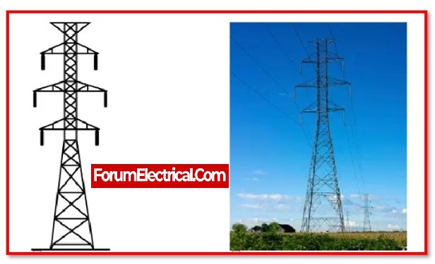
1). Waist type transmission tower
This is the type of transmission tower that is used the most often. It can handle voltages ranging from 110 kV to 735 kV. These towers are perfect for power lines that traverse highly uneven terrain since they are simple and requires minimal maintenance.

2). Double circuit transmission tower
In order to accommodate voltages ranging from 110 to 315 kV, a small-footprint double-circuit tower is used. Its height might vary from around 25 to 60 metres.
3). Guyed-V transmission tower

The voltages that can be accommodated by the Guyed-V tower tower range from 230 to 735 kV. In terms of cost effectiveness, the guyed-V tower outperforms economically than both the double-circuit & waist-type towers.
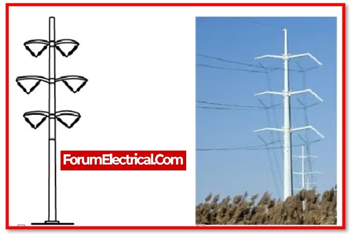
4). Tubular steel pole transmission tower
Tubular steel pole transmission tower has a more streamlined and appealing form than other towers, and it is also less large than the other towers, which allows it to easily integrate into its surroundings. Because of this, it is gaining a steadily increasing significant presence in the urban cores.
5). Guyed cross-rope suspension transmission tower
This guyed cross-rope suspension transmission tower has a simple design and is simple to assemble. The 735-kV conductors that are utilised on certain parts of the power lines. This type of structure needs a lesser number of galvanised steel than the guyed-V tower, which results in it being lighter and having lower overall costs.

Special Type Tower
In addition to the customised type of tower described above, the following unique applications have been considered while designing the tower (Special Type Tower):
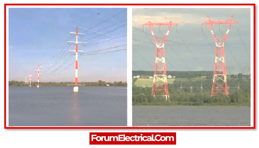
1).River crossing tower
2). Railway (or) Highway crossing tower
3). Transposition tower
Towers are susceptible to being damaged or destroyed by a variety of natural and manmade hazards, including storms, ice, earthquakes, floods, soil erosion, and intentional actions.
Structures within the emergency restoration system are intended to swiftly restore service to lines by avoiding damaged permanent infrastructure in a manner that is both expedient and secure.
The structures that make up the emergency restoration system (ERS) provide the ability to restore or replace permanent structures without being constrained by time.
High Voltage Alternating Current transmission lines
High Voltage Alternating Current transmission lines are utilized for extra high voltage (110- or 115-kV and beyond; in modern systems, 132- or 220-kV and above) AC transmission lines. The towers are constructed in such a way that three (or) multiples of three conductors may be safely worked.
High-voltage direct current (HVDC) transmission lines
High-voltage direct current (HVDC) transmission lines can be
- Monopole systems or
- Bipolar systems.
1). Monopole systems
Single-pole (Monopole) with ground return only allows for the use of a single conductor.
2). Bipolar systems
Bipolar systems have an arrangement of conductors in which there is one conductor on each side of the tower.
Single-phase alternating current railway traction lines
The single-phase alternating current railway traction lines are used by the overhead railway line. The lines are constructed in a way that is similar to that of 132 kV three phase lines. Both concrete poles and steel tubes are viable options for the construction of these lines.
Design of Transmission Towers
Transmission structures come in a variety of designs. There are two common types
1). Lattice Steel Towers (LST)
2). Tubular Steel Poles (TSP)
1). Lattice Steel Towers (LST)
The Lattice Steel Towers are constructed using a steel framework comprising structural components that are welded (or) bolted together.
2). Tubular Steel Poles (TSP)
Tubular Steel Poles (TSP) It is constructed using hollow steel poles, which may either as a single piece or in many portions that be assembled together.
The fundamental requirements to consider before designing the tower are
- Voltage
- The total number of circuits.
- Conductor types.
- Insulator classification.
- The addition of additional circuits in the future.
- The transmission cable is being traced.
- Tower location selection.
- Points of rigidity are to be selected.
- Conductor configuration is chosen.
- Each tower’s height may be customised.
Tower height Selection
The tower design concept focuses on the
- Tower height,
- Base width,
- Top damper width, and
- Cross arm length.
The typical tower height ranges from 15 to 55 metres (49 to 180 ft).
Frequently Asked Questions:
1). How is transmission tower designed?
Enhancing the Efficiency of Design of the Power Transmission Lines by,
- Clearance selection
- Analysis of tower configuration. Based on estimates weight of the tower.
- Design of an insulator and insulator string.
- Economic analysis of the line.
- Analysts of the line cost and optimisation techniques of the span.
- Conductor studles are bundled.
2). Which code is used in design of transmission tower?
In general, the analysis and design of transmission line towers, which are steel lattice structures, followed Indian Standards code IS 802 (Part 1):1995.
Currently, a new version of the IS 802 (Part 1/ Sec 1):2015 code was released for transmission line towers with modified load combinations and material input requirements. In terms of design, analytical effectiveness, and economy, no efforts have been made to compare the original code with the new code.
Utilising the research and design process of earlier and more recent codes, the current study aims to examine the loading, axial forces, deflection, and weight of the tower.
Using STAAD.Pro V8i software and the provisions of earlier and amended regulations, two transmission line towers with the same shape were analysed and constructed.
According to the comparison’s findings, the axial forces at critical locations are reduced by 25 to 40%, 15 to 25%, and 18 to 30% for 132 kV, 400 kV, and 765 kV, respectively, compared to designs based on IS 802 (Part 1/ Sec 1): 1995.
The difference between the tower material’s total weight under the IS 802-2015 design and the IS 802:1995 design is 6.24%, 5.92%, and 5.72% for 132 kV, 400 kV, and 765 kV, respectively.
3). What is the calculation for Transmission line tower design?
During the design process of a transmission tower, the following considerations must be observed to calculate, the actual height of the transmission tower by dividing the entire height of the tower into four equal parts:
- Minimum ground clearance that is permissible for use (H1)
- The maximum sag of the conductor in the overhead (H2)
- There is a space in the vertical position between the top & bottom conductors (H3)
- There must be a vertical clearance between both the ground wire & the top conductor (H4)
H=H1+H2+H3+H4
- The ground clearance & vertical spacing of a transmission line often need to be increased in proportion to the voltage of the line. Hence, high voltage towers will have a higher permitted ground clearance as well as a larger vertical distance between the top & bottom conductors.