
- What is a Transformer?
- Different types of transformers
- EMF Equation of the Transformer
- Turns Ratio of the Transformer
- Voltage Transformation Ratio of the Transformer
- Current Transformation Ratio of the Transformer
- Relationship between Current Transformation Ratio & Voltage Transformation Ratio, & Turns Ratio
- MMF Transformer Equation
- Equivalent Resistance of the Windings of the Transformer
- Leakage Reactance of the Windings of the Transformer
- Equivalent Reactance of the Windings of the Transformer
- Total Impedance of the Transformer’s Windings
- Equations of the Input & Output Voltage of a Transformer
- Transformer Losses
- Voltage Regulation of the Transformer
- Efficiency of the Transformer
- Transformer Efficiency Under All Load Conditions
- All Day Transformer Efficiency
- Condition for the Transformer Maximum Efficiency
- Maximum Transformer Efficiency Corresponding to Load Current
- Conclusion
Transformers are one of the most common types of electrical devices, and they may be found in a variety of applications within the area of electrical engineering, including power systems. Therefore, in the position of an electrical engineer, it is usually needed to compute various characteristics of a transformer in order to establish the circumstances under which it operates. In order to do this, will need to use conventional equations, which can be seen mentioned in the sections that will follow in this post.
What is a Transformer?
A transformer is a static alternating current electrical equipment that is used in electrical power systems for the purpose of altering the voltage level according to the requirements. This might mean increasing or reducing the voltage. The level of the voltage & the current may be changed by a transformer, but the frequency remains the same.
Different types of transformers
A transformer may be classified as one of these three categories according to the way it operates:
- The voltage is raised from a lower level using a step-up transformer, which refers to a step-up transformer.
- The voltage level is lowered by a step-down transformer, which starts at a higher voltage level.
- An isolation transformer is a device that does not alter the voltage but rather electrically isolates two independent electrical circuits. Another term for it is the 1-to-1 transformer.
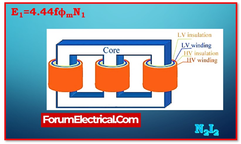
EMF Equation of the Transformer
The term “emf equation of the transformer” refers to the mathematical formula that determines the value of the induced electromagnetic field (EMF) in the windings of the transformer.
The equation for the electromagnetic field of the primary winding is as follows:
E1=4.44fϕmN1=4.44fBmAN1
The equation for the electromagnetic field of the secondary winding is as follows:
E2=4.44fϕmN2=4.44fBmAN2
Where,
f -Supply frequency,
ϕm – Maximum flux in core,
Bm– Maximum flux density in core,
A – Crosssection area of core,
N1 and N2 – Number of turns in primary & secondary windings.
Turns Ratio of the Transformer
The turns ratio of a transformer is defined as the ratio of the number of winding turns in primary side (N1) to the number of winding turns in the secondary side (N2) of the transformer.
Turns Ratio=Primary winding turns(N1)/Secondary winding turns(N2)
Voltage Transformation Ratio of the Transformer
The term “voltage transformer ratio” refers to the relationship between a transformer’s alternating current (AC) output voltage and its alternating current (AC) input voltage. It is denoted as K.
Voltage Transformation Ratio,
K=Output Voltage (V2)/Input Voltage (V1)
Current Transformation Ratio of the Transformer
The term “current transformation ratio” refers to the proportion of a transformer’s output current, which is the current flowing through its secondary winding, to its input current, which is the current flowing through its primary winding.
Current Transformation Ratio,
K=Secondary winding current(I2)/Primary windingcurrent(I1)
Relationship between Current Transformation Ratio & Voltage Transformation Ratio, & Turns Ratio
The following formula indicates the connection that exists between the turns ratio, the voltage transformation ratio, & the current transformation ratio:
Turns Ratio =N1/N2=V1/V2=I2/I1=1/K
In this condition,the voltage transformation ratio is reciprocated by the current transformation ratio.This is because whenever a transformer raises the voltage, it simultaneously lowers the current in the same proportion in order to keep the magnetic field strength (MMF) in the core at a consistent level.
MMF Transformer Equation
Magnetomotive Force denoted as MMF. The transformer’s ampere-turn rating is another name for the mmf. An established magnetic flux in a transformer’s core is created by the mmf. It is determined by multiplying the number of turns in the winding by the current flowing through it.
Primary winding,MMF=N1I1
Secondary winding,MMF=N2I2
Where,
I1-Current in transformer’s primary winding
I2– Current in transformer’s secondary winding
Equivalent Resistance of the Windings of the Transformer
Copper wire is often used in the construction of a transformer’s primary as well as secondary windings. As a result, they do possess a finite resistance, although one that is rather low. R1 is the symbol used to indicate the resistance of the primary winding, while R2 is the symbol used to represent the resistance of the secondary winding.
Referring to the entire circuit of the transformer, either on the primary side or the secondary side, the equivalent resistance of the windings of the transformer is given.
Therefore, the equivalent resistance of the windings on the primary side of the transformer may be calculated as follows:
R01=[R1+R′2]=[R1+(R2/K2)]
The equivalent resistance of the windings on the secondary side of the transformer may be calculated as follows:
R02=[R2+R′1]=[R2+(R1K2)]
Where,
R1 ′ represents the resistance of the primary winding with reference to the secondary side,
R2 ′ represents the resistance of the secondary winding with reference to the primary side,
R1 represents primary windingresistance,
R2 represents secondary windingresistance,
R01 represents the equivalent resistance of the transformer with reference to the primary side, and
R02 represents the equivalent resistance of the transformer with reference to the secondary side.
Leakage Reactance of the Windings of the Transformer
The term “leakage reactance of the transformer windings” refers to the inductive reactance that is induced by the leakage of magnetic flux in the transformer.
With regard to the primary winding,
X1= E1/I1
With regard to the secondary winding
X2= E2/I2
In this equation,
X1 represents primary windingleakage reactance,
X2 representssecondary windingleakage reactance,
E1 representsprimary windingself-induced emf, and
E2 represents secondary windingself-induced emf.
Equivalent Reactance of the Windings of the Transformer
The overall reactance that the primary & secondary windings of the transformer contribute to the total reactance that is referred to as the equivalent reactance.
The equivalent reactance of the transformer, as it applies to the primary side, is as follows:
X01=[X1+X′2]=[X1+(X2/K2) ]
The equivalent reactance of the transformer, as it applies to the secondary side, is as follows:
X02=[X2+X′1]=[X2+(K2X1)]
In this equation,
X1‘ represents the leakage reactance of the primary winding on the secondary side, and
X2‘ represents the leakage reactance of the secondary winding on the primary side.
Total Impedance of the Transformer’s Windings
The term “total impedance of the transformer windings” refers to the opposition that is provided by the combined efforts of the winding resistances & leakage reactance.
The impedance of the transformer’s primary winding stated as
Z1=√R21+X21
The impedance of the transformer’s secondary winding stated as
Z2=√R22+X22
On the primary side of the transformer, the equivalent impedance calculated as follows:
Z01=√R201+X201
On the secondary side of the transformer, the equivalent impedance calculated as follows:
Z02=√R202+X202
Equations of the Input & Output Voltage of a Transformer
In the equivalent circuit of a transformer, the KVL formula is used to get the voltage equations for both the input and output of the transformer.
The equation for a transformer’s input voltage may be written as follows:
V1=E1+I1R1+jI1X1=E1+I1(R1+jX1)=E1+I1Z1
The equation for a transformer’s output voltage may be written as follows:
V2=E2−I2R2−jI2X2=E2−I2(R2+jX2)=E2−I2
Transformer Losses
1). Core loss &
2). Copper loss
are the two different kinds of losses that might take occurs in the transformer.
1). Core Losses
The hysteresis loss together with the eddy current loss contribute to the overall core loss of the transformer, which may be expressed as:
Core loss=Ph+Pe
In such condition, the hysteresis loss is occurred on by a magnetic reversal that occurs in the core.
Hysteresis loss,Ph=ηB1.6maxfV
Additionally, the eddy current is occurred by eddy currents flowing inside the core.
Eddy current loss,Pe=keB2mf2t2
Where,
η – The Steinmetz coefficient,
Bm–Core Maximum flux density,
Ke– Eddy current constant,
f – Frequency of magnetic flux reversal, and
V – Core’s volume.
2). Copper Loss
Copper loss occurs as a result of the windings of the transformer having a high resistance.
Copper loss=I21R1+I22R2
Voltage Regulation of the Transformer
The change in the output voltage of a transformer from no-load to full load is described as the transformer’s voltage regulation, and it is measured relative to the transformer’s no-load voltage.
Voltage Regulation=(No load voltage -Full load voltage)/No load voltage
Efficiency of the Transformer
The transformer’s efficiency is defined as the ratio of the output power to the input power.
Efficiency,η=Output power(Po)/Input power(Pi)
Efficiency,η=Output power/(Output power+Losses)
Transformer Efficiency Under All Load Conditions
The following formula is used to determine the efficiency of a transformer at a specific actual load:
η= x × full load kVA×power factor/(x × full load kVA×power factor)+Losses
All Day Transformer Efficiency
A transformer’s all-day efficiency is defined as the ratio of output energy (kWh) to input energy (kWh) during a 24-hour period.
ηallday=Output energy in kWh / Input energy in kWh
Condition for the Transformer Maximum Efficiency
When a transformer’s core losses & copper losses are equal to one another, the efficiency of the transformer is at its maximum.
Therefore, in order to achieve the transformer’s maximum efficiency
Copper loss=Core loss
Maximum Transformer Efficiency Corresponding to Load Current
The load current (or) secondary winding current for a transformer’s maximum efficiency is provided by,
I2=√Pi/R02
Conclusion
This post explained the most essential formulae of electrical transformers, which are highly important for all learners of electrical engineering and every electrical engineering professional.