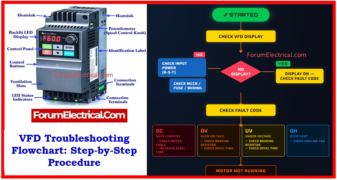
A Variable Frequency Drive (VFD) is an essential device used to control motor speed by varying voltage and frequency.
- Common Causes of VFD Failure
- Root Cause Analysis
- Factors Affecting VFD
- Essential Tools for Troubleshooting VFD
- Step 1: Check VFD Display Status
- Step 2: No Display Condition (Power Issue)
- Step 3: Display ON – Check Fault Codes
- Step 4: Motor Not Running
- Step 5: Check Motor & Cable
- Step 6: Check VFD Parameters
- Step 7: Reset and Monitor
- Preventive Maintenance Tips
- Conclusion
- FAQs
Because of its complex electronics and operating environment faults can occur and must be addressed systematically.
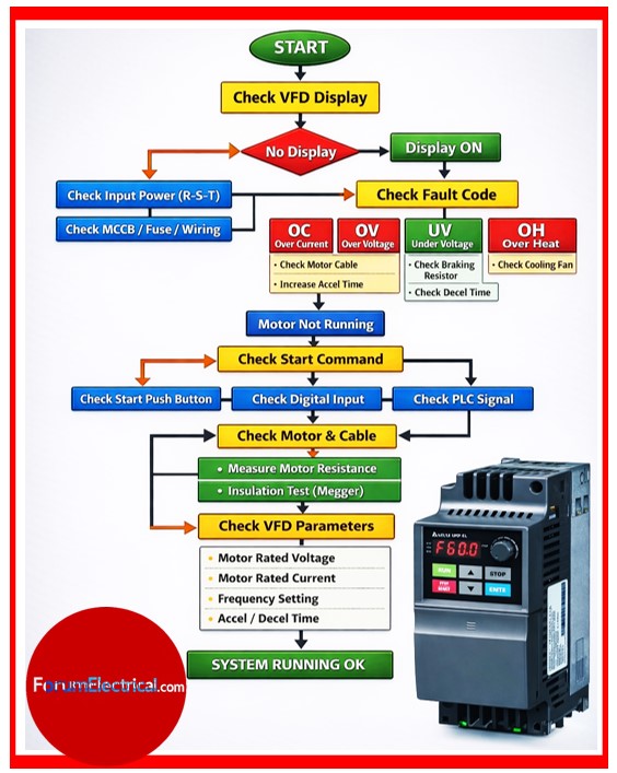
This post provides a clear, field level troubleshooting procedure based on a practical flowchart used by engineers and technicians.
Common Causes of VFD Failure
The most common causes of VFD failure are:
- Loose power connections may lead to unstable operation.
- Voltage imbalance may cause improper functioning of the drive.
- Motor overloading may result in frequent trips.
- High starting current may stress the system components.
- Capacitor aging in DC bus can reduce performance.
- Lack of maintenance may lead to unexpected failures.
Root Cause Analysis
The root cause of the fault must always be identified before restarting the system.
- An overcurrent condition may occur due to mechanical overload.
- An overvoltage condition may result from regenerative energy.
- An undervoltage condition may occur due to supply issues.
- An overheating condition is generally caused by poor ventilation.
Factors Affecting VFD
VFD performance is highly dependent on the environment:
- Dust accumulation may block cooling paths & cause overheating.
- Moisture can lead to insulation failure & short circuits.
- High ambient temperature may reduce component life.
- Poor airflow may result in inefficient cooling of the VFD.
- Proper environmental conditions are more essential for reliable operation.
Regular cleaning & ventilation are essential.
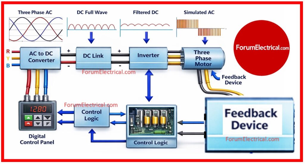
Essential Tools for Troubleshooting VFD
1). Multimeter (DMM)
2). Megger (Insulation Tester)
3). Clamp Meter
4). Thermal Camera (optional)
Step 1: Check VFD Display Status
The first step is to check the VFD display panel carefully.
If there is no display, it indicates a possible power supply issue.
If the display is ON, the VFD will show a fault code or message.
- If no display → Power supply issue
- If display ON → Fault code will be shown
Step 2: No Display Condition (Power Issue)
If the VFD screen is OFF:
- The input power supply should be checked across R, S and T phases.
- The MCCB & fuse condition should be verified to ensure they are not tripped (or) blown.
- All wiring connections should be inspected to confirm they are properly tightened.
- Any loose (or) burnt terminals must be identified and rectified immediately.
- Most no display issues occur due to power failure (or) improper wiring connections.
Step 3: Display ON – Check Fault Codes
When the display is active analyze the fault codes:
Common Faults:
OC – Over Current
- The OC fault indicates an overcurrent condition in the system.
- The motor cable condition must be checked thoroughly for damage (or) short circuit.
- The mechanical load on the motor must be reduced if it is excessive.
- The acceleration time should be increased to prevent sudden current spikes.
OV – Over Voltage
- The OV fault may indicates an overvoltage condition.
- The braking resistor should be checked for proper operation.
- The deceleration time should be adjusted to avoid regenerative voltage rise.
UV – Under Voltage
- The UV fault can indicates an undervoltage condition.
- The input supply voltage should be checked for stability & adequacy.
- Any voltage fluctuation issues should be corrected immediately.
OH – Over Heating
- The OH fault can indicates overheating of the VFD.
- The cooling fan should be checked to ensure it is functioning properly.
- Adequate ventilation should be ensured around the VFD panel.
Step 4: Motor Not Running
If no fault is shown but motor is not running:
- The start command signal must be verified for the proper operation.
- The digital input signals should be tested for the proper response.
- The PLC signal should be verified to ensure correct communication with the VFD.
Control circuit issues are very common issues in automation systems.
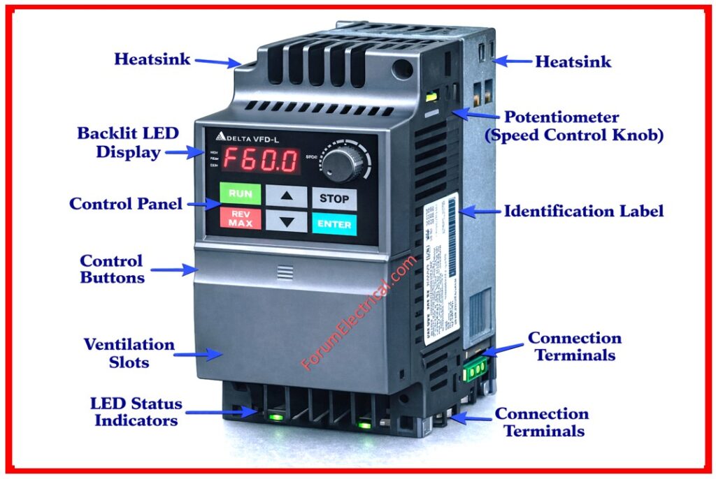
Step 5: Check Motor & Cable
If control is OK but the electric motor still not running:
- The motor winding resistance should be measured to confirm uniformity.
- An insulation resistance test must be performed using a Megger.
- The motor cable continuity must be checked properly.
- The cable must be inspected for any short circuit (or) earth fault.
Step 6: Check VFD Parameters
Incorrect settings can stop operation even if hardware is fine.
- The motor rated voltage should be correctly set in the VFD.
- The motor rated current should match the nameplate value.
- The frequency setting should be configured properly as per application.
- The acceleration and deceleration times should be set appropriately.
- Incorrect parameter settings may lead to improper VFD operation.
Wrong parameters = Improper drive behavior
Step 7: Reset and Monitor
- After fixing the issue:
- The electric drive can also be restarted by performing a safe power cycle.
- The motor should be restarted with a reduced load initially.
Inspect for:
- The system should be monitored closely for any abnormal behavior.
- Repeated faults should be analysed/investigated further before the continuous operation.
Preventive Maintenance Tips
- The VFD should be cleaned regularly to remove dust and debris.
- Adequate cooling should be ensured at all times.
- All electrical connections should be checked & tightened periodically.
- Moisture exposure should be avoided completely.
- Regular inspections should be carried out to detect early faults.
Conclusion
VFD troubleshooting becomes simple when a structured method statement is followed.
- The procedure must always start with checking the display status.
- Power supply and fault codes must be analyzed carefully.
- The motor, cable and parameters must be verified systematically.
- Preventive maintenance functions an important characteristics in avoiding failures.
FAQs
1). What is the most common fault in a VFD?
- Dust accumulation
- Excessive heat
- Poor ventilation (or) airflow
These factors can lead to overheating, insulation failure and internal component damage.
2). Can a bad motor damage a VFD?
Yes a faulty motor can negatively impact the VFD.
For example:
Motor overload can cause overcurrent faults.
Short circuits or insulation failure can damage the drive output stage.
Bearing (or) winding issues can create abnormal current draw.
Proper motor condition monitoring is essential to protect the VFD.
3). How can VFD failure be prevented?
VFD failure can be minimized by following preventive maintenance practices:
- Keep the drive free from dust and debris.
- Ensure proper ventilation and cooling.
- Protect against moisture ingress.
- Maintain clean electrical connections.
4). Why is VFD suddenly not working?
A VFD may stop functioning due to several reasons including:
- Overcurrent during acceleration.
- Undervoltage or power supply issues.
- Overheating due to poor cooling.
- Input (or) output phase loss.
- Internal component failure.
Checking the fault codes & diagnostics is the first primary step in troubleshooting.
5). How to fix an overcurrent fault in a VFD?
To resolve/clear an overcurrent fault:
- Stop the electric drive immediately.
- Check the motor load for any abnormal conditions.
- Inspect wiring for short circuits (or) grounding faults.
- Increase acceleration ramp time.
- Verify motor and drive ratings match.
6). What is the main cause of VFD failure?
The primary causes of VFD failure are harsh environmental conditions such as:
- High ambient temperature.
- Moisture and humidity.
- Dust and contamination.
These conditions reduce component lifespan and reliability.
7). What are the maintenance steps for a VFD?
Regular VFD maintenance should include:
- Cleaning dust and debris from cooling fans and heat sinks.
- Checking for moisture (or) condensation.
- Tightening electrical connections.
- Monitoring operating temperature.
- Inspecting cables and terminals for wear (or) damage.

