
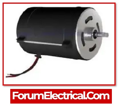
What is DC Motor?
A DC motor is a type of electric machine that transforms an electrical energy into a mechanical energy. Direct current motors use direct current to convert electrical power (electrical energy) into mechanical rotation (mechanical energy).
Why regulate the speed control of a DC motor?
It is possible for the motor to produce large currents if the torque and current of the DC motor are not controlled. This may often result in torques being supplied that are in excess of that which is mechanically feasible for the system, which could potentially lead to the system failing (this is especially apparent when gear with a big reduction ratio is employed).
DC Motor Speed Control Methods
The equation below determines the DC motor’s speed.
N = (V-IaRa)/ kØ
Where,
N – DC motor’s speed
Ia – Current flow through armature
Ra – Armature Resistance
V – Voltage across armature
K – Constant and
Ø – Magnetic Flux
From the equation that
- Changing the flux, which may be accomplished by modifying the field current (the flux control method),
- Changing resistance of the armature (Armature control method), and
- Changing voltage supply (Voltage control method),
would cause the DC motor to run at a different speed.
How to control DC Motor Speed?
The speed control of a DC motor varies depending on the type of DC motor. The methods that are applied in all categories are outlined.
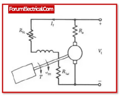
1). Flux Control Method
In this method, to regulate the speed of the motor, change the magnetic flux. This can be done by changing the current via the field winding.
In order to accomplish this, can connect a resistor in series connection with the field winding and adjust the resistance to control the current, which in turn controls the field eventually regulating the speed of the dc motor.
When resistance is reduced to a minimum, current flows through the field winding increases, and consequently flux increases and speed decrease.
2). Armature Control Method
In this method, the armature winding and a variable resistor are connected in series with one another.
The voltage that is applied across the armature, and therefore the speed, will vary whenever there is a change in the resistance. According to ohm’s law, the speed of the motor increases if the resistance of the variable resistor is reduced.
This will cause an increase in the voltage drop that occurs across the armature winding.
In the same way, increasing the value of the variable resistor results in a decreasing in both the voltage drop across the armature winding and the speed of the electric motor.
3). Voltage Control Method
By providing a PWM signal, also known as pulse width modulation, the voltage that is found across the motor could be varied.
This pulse-width-modulated signal, or PWM, may be produced by any microcontroller (or) IC 555.

Using Arduino and the analog write(value) function is the simplest and most effective method to do it.As a result, the pulse width can be varied. PWM decreases the speed control as width increases.
Common DC Motor Problems & Troubleshooting
Although being simple machinery, DC motors need regular maintenance to extend their functionality and that of their facilities.
Users of DC motors in the industrial industry are all too familiar with the difficulties that might arise while troubleshooting problems. Most typical DC motor problems are fixed by troubleshooting.
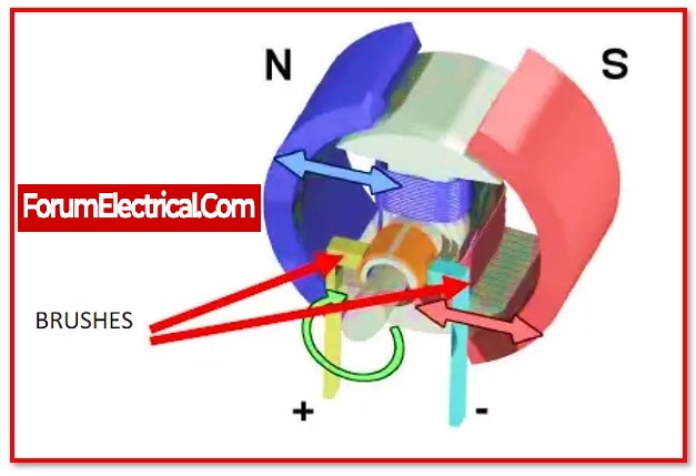
1). Carbon Brushes
Problem:
The appropriate quantity of load must be applied to DC motors. This is essential to maintaining a specific level of lubricity between the brushes and the commutator while under load, as well as for brush conductivity on the commutator & current density.
Cause:
The motor’s carbon brushes may prematurely wear out and build up carbon dust if the applied load is irregular and the motor’s brushes are of the improper grade. The commutator bars may get irreparably damaged as a result of this problem. To find the best brush grade for each of your applications, a carbon brush survey may be useful.
Troubleshoot:
- In order to prevent early wear on the brushes, it is also essential to maintain correct, consistent pressure on the brush to the commutator in order to supply the maximum current density at the point of contact.
- To preserve the insulation and avoid poor megohmmeter readings, carbon dust must be removed from within the motor. Carbon dust is detrimental to the insulation.
- Using compressed air to assist clear any leftover dust from within the engine can help avoid carbon buildup.
- The DC drive may be alerted to turn off the power to warn of a possibility to ground by receiving a very low megohmmeter value.
2). Brush Rack Adjustment
Problem:
It is essential that the rack or yoke component be correctly set to a position is known as the “neutral” position.
In order to achieve this result, will need to arrange adjacent brushes on the commutator in an area that is either outside of or in between the polarity reference of the armature coils that are being energised with voltage across the brushes.
Cause:
When under stress, maintaining the brushes in a neutral position may help prevent excessive arcing from occurring. It might be challenging to get the balance correct while switching loads.
Troubleshooting:
On-site adjustments and procedures for setting the neutral may be carried out whenever they are required.
3). Commutator Maintenance

Problem:
Like carbon brushes, the commutator needs periodic maintenance. Segmented commutator bars must be machined accurate to maintain them. Moulding mica insulates the bars.
To avoid motor extraction, certain bigger DC motors may be developed onsite. To maintain the commutator circular without surface run-out, adequate maintenance is essential.
Carbon particles will accumulate between the commutator’s bars, creating the potential for a bar-to-bar short.
Cause:
Brushes and springs may break if the commutator eccentricity is too high. High bars may damage brushes and create excessive arcing when the brush impacts the copper bars if the commutator is out of round.
Troubleshooting:
- To avoid brush damage to the commutator, use a well-balanced armature.
- When machining a commutator, it is generally preferable to under-cut the mica insulation between each bar and chamfer the upper margins of the sides. This will provide a smooth contact surface for the carbon brushes.
- Keeping the eccentricity of the commutator to a minimum will result in an extended duration.
4). Winding Issues
Problem:
Failure of the field winding or the interpole winding is another typical problem that may occur with DC motors. Both types of winding have the potential to emerge as arcing at the brushes.

Cause:
It is possible to run into issues with the field windings overheating if a DC motor is allowed to remain idling and the drive is not configured to include a field weakening option.
Troubleshooting:
A large number of medium-sized and larger DC motors will come equipped with a blower system of some type to assist with reduce this problem.
5). Mechanical DC Motor Issues
- An electric motor has to be properly maintained mechanically just like any other motor. For life expectancy, adequate lubrication and maintenance must be performed on bearings.
- In order to prevent bearing problems, such as misaligned bearing retainers or incorrect attachment of the stator to the end frame, the motor must also be put together properly.
- The motor must be installed and aligned properly in order for it to continue operating at its best efficiency.
6). Drive Maintenance
Problem:
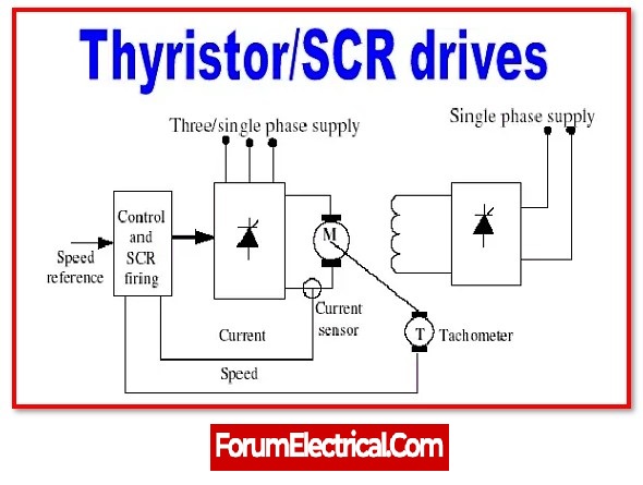
A DC motor that is not efficient may also be caused by DC drives. Excessive arcing from the brushes to the closest ground or metal surface inside the end frame on the commutator side of the motor might indicate problems with the silicon-controlled rectifiers (SCRs) in a drive.
Cause:
DC drives are designed according to the load’s horsepower, voltage, and amperage requirements.
A mounted tachometer that is attached to the motor shaft’s end is another alternative for the drive.
The motor may enter an overspeed state due to over-voltage at the armature if the tachometer (or) drive connections are not correctly terminated.
Troubleshooting:
- The drive will respond when there is a small voltage, or even no voltage, generated by the tachometer.
- DC drives are intended to turn off the motor in critical conditions such as this one.
How to Troubleshoot and Prevent DC Motor Failure?
- Maintain the flow of production by learning to diagnose and regulate the speed of DC motors.
- Avoid the most frequent errors made while installing and maintaining brushes.
- Learn how to recognise an SCR problem in a DC drive’s power bridge.
- Explore how noise might interfere with a DC drive’s performance and understand how to eliminate it.
- Understand the circuits and parts involved in the 3 most prevalent ways to decelerate a DC motor.
- Restore full-voltage and low-voltage DC motors to service as soon as possible
Conclusion
In general,
- A DC motor is an independent motor.
- DC motor are simple and complexity.
- Brushes, brush springs, and the commutator will always require proper maintenance.
