
What is meant by grounding conductor?
- What is meant by grounding conductor?
- What is the use of grounding conductor?
- What is the difference between a grounding conductor and grounded conductor?
- What is the color of a grounding conductor?
- Which standards are used to specify grounding conductor?
- How to size a grounding conductor?
- Formula for sizing of ground conductor
- Grounding conductor selection process
- Which grounding conductor is appropriate for utility applications?
- Why is a grounding conductor used?
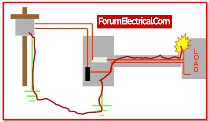
A grounding conductor is an electrical conductor that is used to connect a device or system to the earth or to some other reference point that is at zero potential. The purpose of grounding is to provide a low-impedance path to the earth that can safely carry any stray current that may be present in the electrical system. This helps to prevent electrical shocks, fires, and other hazards that can be caused by stray current.
Grounding conductors can be used in various electrical systems such as buildings, power distribution systems, and electronic equipment.
There are several types of grounding conductors such as:
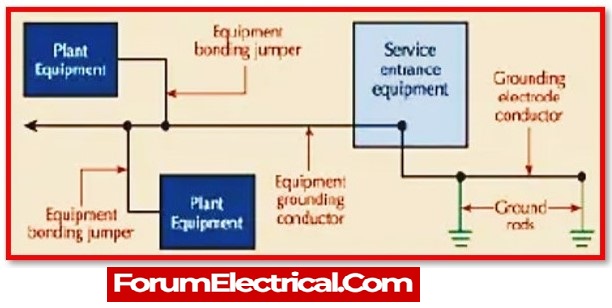
1). Equipment grounding conductor
This conductor connects the non-current carrying metal parts of equipment to the grounding system.
2). Grounding electrode conductor
This conductor connects the grounding system to a grounding electrode such as a rod, pipe, or plate that is buried in the earth.
3). Service equipment grounding conductor
This conductor connects the grounding system to the service equipment, such as the service entrance panel.
4). Bonding conductor
This conductor connects the grounding system to the neutral conductor and helps to ensure that the neutral and grounding conductor are at the same potential.
What is the use of grounding conductor?
The use of a grounding conductor is to provide a safe and low-impedance path to the earth for any stray electrical current that may be present in an electrical system. This helps to prevent electrical shocks, fires, and other hazards that can be caused by stray current.
Grounding conductors are used in various electrical systems such as buildings, power distribution systems, and electronic equipment. The main uses of grounding conductors are:
Safety: Grounding conductors provide a path for stray current to safely return to the earth, reducing the risk of electrical shock or fire.
Overvoltage protection: Grounding conductors can provide protection against overvoltage’s caused by lightning, power line transients, or other sources.
Operation of electrical equipment: Many electrical devices and systems require a ground connection to function properly.
Compliance with codes and regulations: Grounding conductors are required by codes and regulations such as the National Electric Code (NEC) to ensure that electrical systems are safe and comply with industry standards.
Preventing equipment damage: Grounding conductors help to prevent damage to electrical equipment by providing a path for any stray current to safely return to the earth.
Improving system performance: Grounding conductors can improve the performance of electrical systems by providing a stable reference point for voltage measurements and reducing noise in electronic systems.
It’s important to note that proper grounding is crucial for the safe operation of electrical systems and equipment. Improperly installed or maintained grounding conductors can cause serious hazards.
What is the difference between a grounding conductor and grounded conductor?
A grounding conductor and a grounded conductor are similar in that they both provide a connection to the earth or to a reference point that is at zero potential, but they have different uses and functions.
A grounding conductor is an electrical conductor that is used to connect a device or system to the earth or to some other reference point that is at zero potential. The purpose of grounding is to provide a low-impedance path to the earth that can safely carry any stray current that may be present in the electrical system. This helps to prevent electrical shocks, fires, and other hazards that can be caused by stray current.
A grounded conductor, on the other hand, is an electrical conductor that is intentionally connected to the earth or to some other reference point that is at zero potential. The purpose of connecting a conductor to the earth is to establish a reference point for the electrical potential of the system. This is often used as a neutral point in a three-phase electrical system or as a reference point in electronic equipment.
In summary, a grounding conductor is used to safely conduct stray current to the earth, while a grounded conductor is used to establish a reference point for the electrical potential of the system.
What is the color of a grounding conductor?
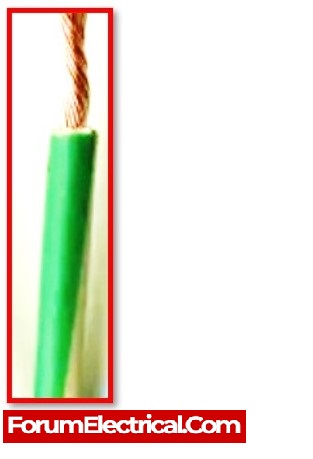
The color of a grounding conductor is typically green or bare. The National Electric Code (NEC) and other industry standards specify that grounding conductors must be identified by a distinctive color, green or green with one or more yellow stripes, or by other effective means.
Bare copper conductors are also used as grounding conductors, in this case, the conductor is not covered by any insulation or jacket, it is exposed copper wire.
It’s important to note that the use of green or bare color for grounding conductors is not only a standard but also an important safety feature, it allows electricians and other maintenance personnel to easily identify the grounding conductor, reducing the risk of errors during installation and maintenance of the electrical system.
Which standards are used to specify grounding conductor?
The National Electric Code (NEC) is the primary standard used to specify grounding conductors in the United States. The NEC provides requirements for the selection, installation, and inspection of grounding conductors in electrical systems.
The NEC is published by the National Fire Protection Association (NFPA) and is adopted by states and municipalities across the United States as the standard for the safe installation of electrical systems. The NEC is updated every three years, and the most recent version is NEC 2017.
- IEEE (Institute of Electrical and Electronics Engineers) Std 80 – IEEE Guide for Safety in AC Substation Grounding
- ANSI/UL 467 – Grounding and Bonding Equipment
- ASTM B8 – Standard Specification for Concentric-Lay & Stranded Copper Conductors, (Hard, Medium-Hard, or Soft)
- IEC 60364-4-41 – Electrical installations of buildings – Part 4-41: (Protection for safety) – (Protection against electric shock)
These standards provide detailed information on the selection, installation, and inspection of grounding conductors, including specifications for conductor materials, sizes, and ampacity. It’s important to consult these standards when designing or maintaining electrical systems to ensure compliance with safety and performance requirements.
How to size a grounding conductor?
The size of a grounding conductor is determined by the National Electric Code (NEC) and other industry standards, which provide specific requirements for the ampacity (current-carrying capacity) of grounding conductors based on the type and size of the electrical system.
The NEC provides tables that list the minimum ampacity requirements for grounding conductors based on the size of the electrical service and the type of electrical system. For example, the NEC Table 250.66 lists the minimum ampacity requirements for grounding conductors for electrical services up to 600 volts.
Sizing of grounding conductors can also be done using calculation methods. There are several methods for calculating the ampacity of grounding conductors, including the “Maximum Fault Current” method and the “Total Current” method.
The size of the grounding conductor can also be determined by the National Electric Code (NEC) based on the size of the service entrance conductors and the overcurrent protection device. This can be found in NEC table 250.122.
| NEC TABLE | ||
|---|---|---|
| Automatic over-current device rating or setting in the circuit ahead of equipment, conduit, etc. Not to Exceed Ampere | (AWG or kcmil) Size | |
| COPPER | ALUMINIUM | |
| 15 | 14 | 12 |
| 20 | 12 | 10 |
| 60 | 10 | 8 |
| 100 | 8 | 6 |
| 200 | 6 | 4 |
| 300 | 4 | 2 |
| 400 | 3 | 1 |
| 500 | 2 | 1/0 |
| 600 | 1 | 2/0 |
| 800 | 1/0 | 3/0 |
| 1000 | 2/0 | 4/0 |
| 1200 | 3/0 | 250 |
| 1600 | 4/0 | 350 |
| 2000 | 250 | 400 |
| 2500 | 350 | 600 |
| 3000 | 400 | 600 |
| 4000 | 500 | 750 |
| 5000 | 700 | 1200 |
| 6000 | 800 | 1200 |
It’s important to note that it’s not only the ampacity of the grounding conductor that is important, but also the material the grounding conductor is made of, the NEC also provides specifications for the material of grounding conductors, such as copper or aluminum.
There are several tools and methods that can be used to calculate the size of a grounding conductor. These include:
NEC Table 250.66: This table provides the minimum ampacity requirements for grounding conductors for electrical services up to 600 volts. The table lists the minimum ampacity for grounding conductors based on the size of the electrical service and the type of electrical system.
Maximum Fault Current Method: This method calculates the ampacity of the grounding conductor based on the maximum short-circuit current that the electrical system can produce. This method takes into account the type of overcurrent protection device used in the system and the size of the service entrance conductors.
Total Current Method: This method calculates the ampacity of the grounding conductor based on the total current flowing through the system. This method takes into account the load on the electrical system and the number of circuits in the system.
Software tools: There are various software tools that can be used to calculate the size of grounding conductors. These tools typically use the Maximum Fault Current Method or the Total Current Method and they can be used to perform more complex calculations and provide detailed reports of the results.
Formula for sizing of ground conductor
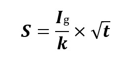
Where,
S = Cross sectional area of bare conductor in mm²
Ig= Ground Fault current in Amps
t = Duration of fault in Seconds
k = Current density of conductor in Amp/mm³
k for Copper = 205 A/mm²
k for Aluminum = 126 A/mm²
k for Steel or GI = 80 A/mm²
Grounding conductor selection process
Both of the following steps should be included in the grounding conductor selection process:
Using the National Electric Code’s recommendation, which specifies that selecting a conductor to satisfy a ground fault will also sufficient for lightning. This is due to the lightning’s high-current pulse’s much shorter duration.
Important to remember that fault currents travel far faster than typical AC steady currents. Rapid current at high speed generates a lot of heat. Such heat must be controlled more efficiently by the conductor than conventional transmission and distribution line currents.
- Copper,
- Copper over welded steel,
- Aluminium,
- Aluminium conductor steel reinforced, and
- Galvanised steel
are the most often used grounding conductors.
1). Galvanized Steel
Galvanized steel wire and cable are inexpensive yet have a low conductivity. Galvanized material (zinc melted onto steel) does not last due to micro cracks and pitting that allow moisture to detach the zinc from the steel and perhaps create stray voltage circumstances. This wire is a poor conductor and should not be used for grounding in utility applications.
2). Aluminum Conductor (Reinforced Steel)
This is widely utilized in high-voltage transmission. Deliver relatively low-current alternating current through these power cables, though. A conductor that can handle rapid temperature rise in 500 milliseconds or less – presumably the longest fault clearing time – is required for grounding. Aluminum has a melting point of 1,220 degrees Fahrenheit, while copper has a melting point of 1,980 degrees Fahrenheit, and steel has a melting point of 2,500 degrees Fahrenheit. Aluminum is electrically sufficient in most power-conducting circuits, but it cannot withstand the heat generated by fault currents or lightning. Based on metal melting points and the high heat generated by high current, copper or copper over steel is the better choice.
3). Welded Copper-Clad Steel
Due to the IEEE 80 formula, which applies equally to copper and copper-clad steel, it is frequently regarded as a lower-grade grounding conductor when compared to copper.
4). Stranded Copper Cable
This is the most commonly used conductor. Copper stranded cable or wire has the highest fusing current and electrical efficiency of the widely researched conductors for the same size conductor as copper-clad steel.
Which grounding conductor is appropriate for utility applications?
Appropriate grounding is a key component of every circuit and must be taken into consideration.
1). Longevity
Because of electricity system failures, service longevity has become increasingly critical. Replacement maintenance has grown increasingly expensive and is often ignored as some utilities address risk management vs cost considerations. This points to the importance of component/material lifespan in new circuit design parameters.
2). Reliability
Longevity and reliability go with each other. It requires a conductor that will perform well over the service conditions.
3). Electrically Sufficient
Why is a grounding conductor used?
To ground noncurrent-carrying metal portions of equipment, use an equipment-grounding conductor (EGC). Its purpose is to keep the equipment as close to ground potential as feasible while also providing a safe path for ground-fault current to flow.