, teleprotection, synchrophasors, & smart grid systems, to assure the power system's reliability and efficiency.)

Communication for Power System
Communication has always been essential in power systems, and it will be even more important when building an end-to-end, 2-way open communication grid architecture. Power-system communications are fundamental to the electric grid’s safety and efficiency.
- Real-time automation and
- Control of electric utility generation, transmission, and distribution systems
require dependable and secure communication networks. To control and protect the power system, the data collected by the outside devices is transferred to the control center using the appropriate communication technique. Communication is an enabling technology that contributes significantly to the modernization & atomization of the electrical power system. In this post, we will discuss the majority of current communication systems that are useful for providing accurate and precise control over the operation of the power system.
- Telecommunication
- SCADA (Supervisory Control and Data Acquisition System)
- EMS (Energy Management System)
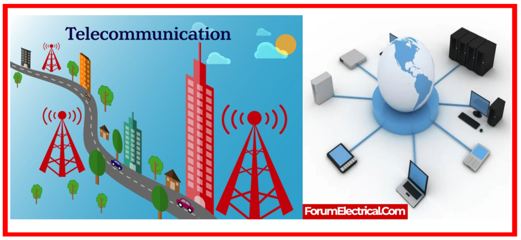
Telecommunication
There are 3 distinct types of telecommunication networks.
- Microwave Communication System
- Fiber-optic Communication System
- PLCC (Power Line Carrier Communication)
Voice Frequency (VF) channels from all of these systems are being integrated/interconnected to form a hybrid communication system.
Microwave and fiber optic communication systems have multiple channels and are also known as ‘wideband communication systems’.
PLCC is a single-channel communication system.
1). Microwave Communication Systems
Microwaves travel across space, and any object that gets in their path can impede the communication system.
Microwave is known as a ‘line-of-sight’ communication method.
As a result, its antennas are positioned on high towers, ensuring that even trees do not block the course of microwaves.
Antenna height is computed using a variety of criteria, including the
- Distance between two spots,
- Path clearance levels,
- Height from sea level of these spots,
- Tropical area,
- Reflection spots, and so on.
As a result, tower heights vary depending on location. Previous analogue microwave technology was employed with a ‘frequency diversity’ system, in which the frequencies of the transmitters and receivers of ‘Normal’ & ‘Standby’ equipment differed.
In a frequency diversity system, both transmitters and receivers are concurrently attached to one antenna. In modern digital microwave system, the transmitters and receivers of ‘normal’ & ‘standby’ equipment have the same frequency, which is known as a ‘hot standby’ system.
Only one column has equipment with the same frequency, which is known as a ‘hot standby’ arrangement.
Only one column is connected to the antenna. Microwaves are subject to the ‘fading phenomena’ caused by changes in the atmosphere above the planet during the day and night, as well as from season to season. Some lines, suspected of severe fading during signal propagation, have been equipped with additional antennas for ‘space diversity’.
Transmitters and receivers in a space diversity system have extra antennas at varying heights. Each system has its own advantages.
The new digital microwave system includes numerous handy features for simple maintenance. Its network management system facilitates remote diagnosis, operation, and maintenance.
2). Fiber Optic Communication Systems
It is a new communication system that has been implemented.
Optical fiber cable, in the type of optical fiber composite ground wire (OPGW), has been put on transmission towers to replace earth wire.
The OPGW in our system contains 12 – dual window single mode (DWSM) fibers. Optical transmissions of 1310 (or) 1550 nanometer (nm) wavelengths are being employed.
A multi-channel link across 2 stations requires only two fibers.
One fiber is utilized to send optical signals, and the other is used to receive signals from the opposite end.
In our system, two fibers are used for the ‘Normal’ communication line and two fibers for the ‘Protection’ path.
Fiber optic communication systems have a large bandwidth transmission capability.
Two fibers are enough to provide over a lakh telephone channels on either side. As a result, high-speed data with vast amounts of information might be transferred at a reasonable cost.
3). Power Line Carrier Communication System (PLC)
Power Line Carrier Communication (PLC) is a single channel communication system in which the channel (300 to 3400 Hz) is divided into two halves, with the voice band (300 to 2400Hz or 300 to 2000Hz) and the rest utilized as data band.
In comparison to a wideband communication system, PLCC has a small speech band and so provides poor quality voice.
In this system, signals go from one end of the transmission line to the other. The transmitter output is fed into the transmission line via a coupling capacitor (or) CVT.
The RF power output ranges in frequency from 70 KHz to 500 KHz. The signals are terminated with inductors known as ‘Wave Traps’. PLCC is also used to transmit line protection signals.
Protection signals pass through the PLCC system to trip the circuit breaker at the opposite end of the transmission line.
SCADA System
SCADA systems send measured values (V, Hz Transformer tap position, MW, MVAR) and open/closed status information (circuit breakers/Isolators position, on/off status) to sub-LDCs via communications channels.
RTUs have been installed at 400KV, 220KV, and a few critical 132KV substations for this purpose. Apart from 33KV Bus isolator position & LV side generators, system values & status information under 132 KV are not transmitted.
Current and potential transformers’ secondary sides are coupled to transducers.
Transducers produce 4mA to 20mA dc current. The analog-to-digital converter turns the current into binary pulses.
The RTU CPU receives consecutive inputs. RTU sends digital pulses to subLDC via communication lines. Depending on the communication link, RTU output is connected directly or via Modem to communication equipment.
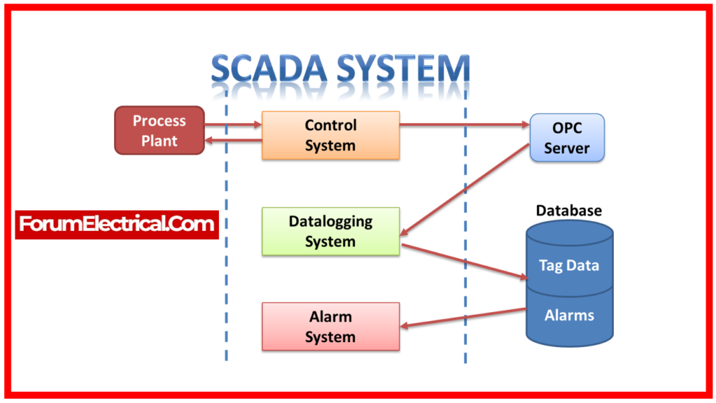
The subLDC feeds RTU data to the data servers. SCADA systems typically have databases, displays, and supporting programs.
A communication mechanism links Sub-LDC’s computer to all RTU stations under its management. ‘Communications’ handles
- RTU Polling,
- Message Formatting,
- Polynomial Checking, And
- Failure Retransmission.
Data Processing: Data is processed after communication. Data process contains three sub-functions:
- Measurements,
- Counters, and
- Indications.
Measurements: RTU measurements get converted to technical units & linearized if needed. The measurements are stored in a database and evaluated against limits, which trigger high (or) low limit alarms.
Counters: The system collects ‘Counters’ every 5 (or) 10 minutes. After the hour, units are moved to a 24-hour archive/history.
Indications: Indications mark status changes & protection. If the status is not alerts, records the change on the printer and adds it to a cyclic activity list. In the sub-LDC, an audio alarm is generated & the appropriate alarm list and activity list are updated for alarms statuses.
Alarm/Event Logging: SCADA data processing uses alarm and event tracking. Alarms have distinct classifications and priorities. For limit violation and status changes, freshly received data receives quality codes. LDCs accept alarms from single-line diagrams or alarm lists on display terminals.
Manual Entry: Important substations/powerhouses that are uncovered by an RTU or have a problem with their RTU, equipment, communication path, etc. can manually enter measured data, counters, and indications.
Averaging of Measured Values: The SCADA system may average all analog values. A 24-hour trend is usually stored by averaging 15-minute measured data.
Historical Data Recording (HDR): The HDR subsystem records selected system parameters over time. Data is collected at a predetermined interval and stored in a historical database. Finally, data is retained for analysis and report generation.
Interactive Database Generation: An offline SCADA database can be changed to incorporate new RTUs, pickup sites, and communication channels.
Supervisory Control (or) Remote Command: This capability enables remote control commands to be sent to substation and powerhouse equipment, such as causing circuit breakers to trip. This system has this function.
Failover: A ‘Fail-over’ subsystem secures and maintains a device and backup database. The device’s ‘online’ or ‘failed’ status is retained. ‘Backup’ maintains database on backup machine and duplicates system.
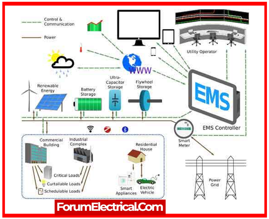
Energy Management System (EMS)
Application software engineers and control engineers utilize EMS software to manage power system energy utilizing SCADA data from the database. The app uses energy management platform. All servers run ‘Open VMS’. All PCs run ‘Window NT’. Key features are below:
The database compiler delivers efficient, consistent data for applications. The database compiler checks entries for completeness & consistency and prepares special tables for application program efficiency.
Most unique is this system’s ‘Sequence of Events’ (SOE) recording. RTUs can properly time tag status changes and notify sub-LDC. All system RTUs are ‘time synchronized’ with the master. All sub-LDCs and SLDCs employ GPS. If tripping occurs, events can be sequenced on a 10-millisecond time scale.
Area Control Error (ARE) is used by automatic generation control (AGC) to control generating units. Departures in standard frequency (50 Hz) and scheduled area interchanges from actual frequency & actual area interchanges determine it.
The ‘Operation Scheduling’ application software has ‘short-term’ & ‘long-term’ system load forecasting functions to help dispatching estimate loads one to several days in advance. This function efficiently schedules resources scientifically and logically.
Application software engineers can estimate weekly peak demands & load duration curves for months using ‘Short-term Load Forecasting’.
Monthly peak demands & load duration curves for a long time using long-term load forecasting.
The EMS software system can also be used for network topology, state estimation, optimal power flow (OPW), stability, power flow displays, assistance & instructional displays, single line diagram displays, tabular displays, etc.
The IEEE Standards Association published IEEE 1675-2008, a standard for broadband over power lines. It offered electric utility companies with a detailed standard for properly putting Internet access gear over their power lines.
Applications of Power System Communications
In order to lower the cost of building new networks, PLC technology is extensively employed in the following systems:
- Smart Building,
- Smart Factory,
- Smart Grid,
- Smart City
- Systems for Advanced Metering Infrastructure (AMI)
- Micro inverters
- Air conditioning
- Lifts
- Storing batteries
- Intelligent street lighting
- Control systems for lighting
- Communication systems
- Cameras for security