")
- What is a Static VAR Compensator?
- Design
- What is the Working Principle of a Compensator?
- Construction of SVC
- Working of the Static VAR Compensator
- Operation of the Static VAR Compensator
- Static VAR Compensator VI Characteristics
- Advantages of Static VAR Compensator
- Disadvantages of Static VAR Compensator
- Applications of Static VAR Compensator
What is a Static VAR Compensator?
A static VAR compensator consists of a controlled reactor & a fixed shunt capacitor connected in parallel.
The reactor is controlled by the SVC’s thyristor switch assembly.
The firing angle of thyristor determines the voltage along the inductor and, as a result, the current flowing through it.
This allows you to control the inductor’s reactive power demand.
This is a parallelly connected static form of VAR absorber or generator whose output is adjusted to replace inductive (or) capacitive current, thereby regulating or managing associated current factors, primarily the bus voltage factor.
A static VAR compensator depends on thyristors that lack gate switching capability.
Thyristor functionality and features grasp the SVC changeable reactive impedance.
This device includes two critical pieces of equipment: TCR and TSR, which are thyristor-controlled capacitors and reactors.
In case of high-voltage electrical transmission lines, the device provides quick reactive power. SVCs are classified as dynamic
AC transmission networks with voltage regulation and system stability.
The fundamental static VAR compensator circuit schematic is illustrated below:
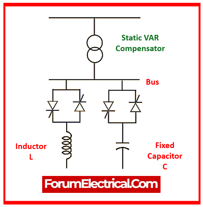
The device’s thyristor switch assembly governs the reactor, while the firing angle regulates the voltage & current values that pass through the inductor. This allows the inductor’s reactive power to be controlled.
This technology has the capacity to eliminate reactive power regulation even over long distances while maintaining zero-time delays. It improves system stability and power factor.
Some of the schemes used by SVC devices include:
- Thyristor-regulated capacitor
- Thyristor-regulated reactor
- Self-reactor
- Thyristor-regulated reactor with a constant capacitor
- Thyristor-regulated capacitor and reactor
Design
In the single-line diagram of the SVC, the reactor may be a shifter internal to the circuit via PAM modulation by the thyristors, resulting in a constantly variable type of VAR to electrical system. In this mode, capacitors govern extended voltage levels, which is well recognized for supplying efficient control.
As a result, the TCR mode gives better control and reliability. Thyristors can also be electronically regulated.
Thyristors, like semiconductors, deliver heat and utilize deionized water to cool them down. When reactive load is sliced into the circuit, it introduces undesired harmonics, and a wide range of filters are typically utilized to smooth out the wave.
Because the filters have capacitive operation, they will transfer MVAR to power circuit.
The structure of the block diagram is illustrated as follows:
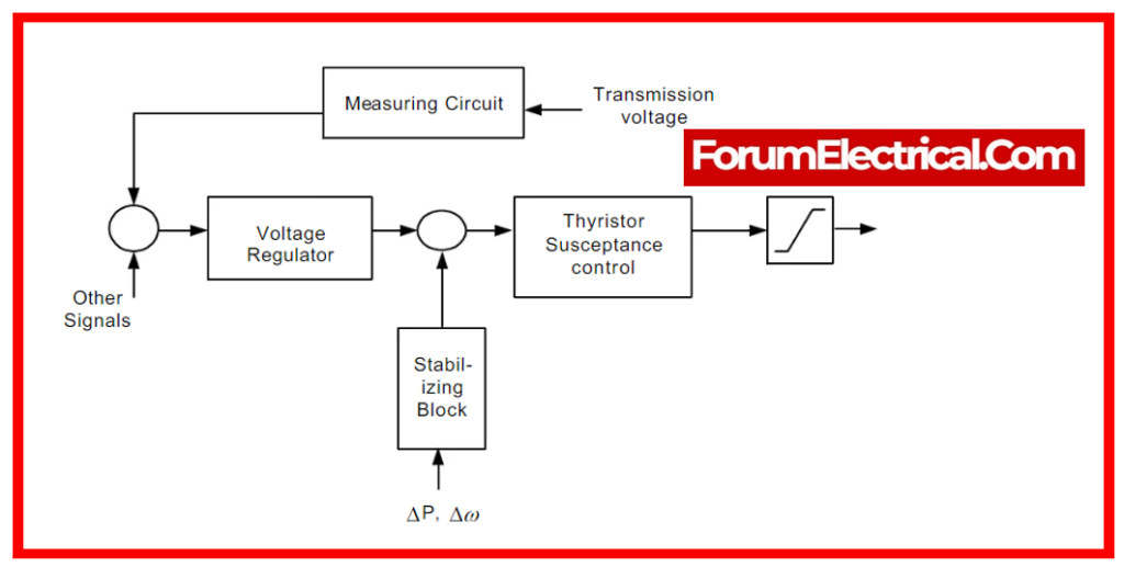
The device comes with a control system that includes:
- A distribution section identifies the thyristor switched capacitors & reactors that need to be switched internally and externally, and calculates the firing angle.
- A synchronization section includes a phase-locked loop that is synchronized on the pulse generator & the secondary level of voltages, where they send a needed number of pulses to the thyristors.
- A calculating portion determines the positive ‘+’ voltage that needs to be regulated.
- A voltage control system that measures the difference between calculated & reference voltage levels.
A phasor simulation technique that is carried out using a powerful section is required to be utilized in order to operate the SVC equipment. It can also be used in 3-phase power networks with synchronous generators, dynamic loads for the execution, and the device’s electromechanical variations.
High-end static VAR compensators may also be built for accurate voltage regulation. A closed-loop controller allows you to control the voltage.
It is the static VAR compensator configuration.
What is the Working Principle of a Compensator?
Static VAR Compensator function in electronic power supply systems is
- To improve the grid’s power factor,
- Reduce losses in power transformers and transmission lines,
- Increase power supply efficiency, and
- Improve the power supply environment.
As a result, reactive power compensation devices are vital and essential components in power supply systems. A rational selection of compensating devices can reduce network losses & improve grid quality. In contrast, inappropriate selection or use may result in issues such as voltage swings and higher harmonics in the power supply system.
Construction of SVC
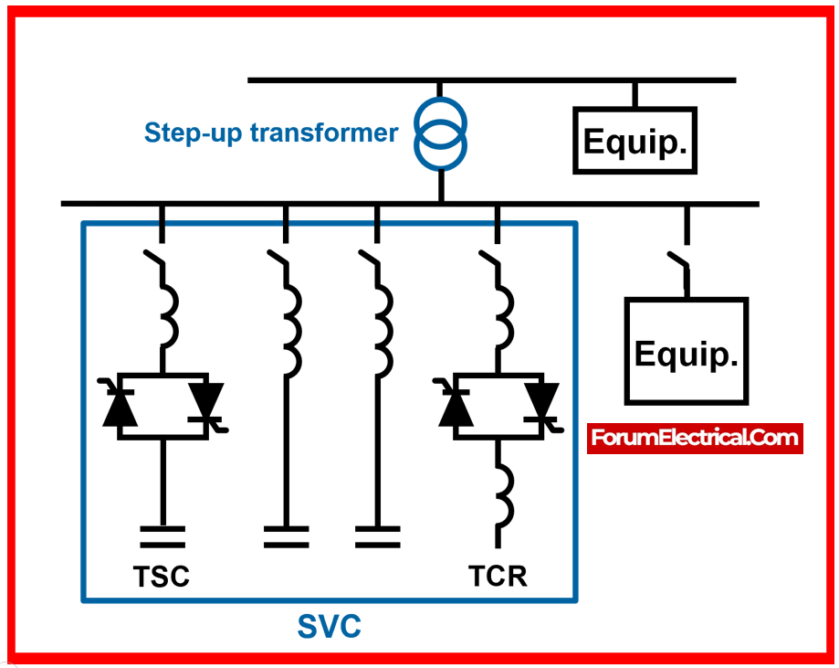
A Static VAR Compensator (SVC) is normally made up of various components, such as a
- Thyristor-Controlled Reactor (TCR),
- Thyristor-Switched Capacitor (TSC),
- Filters,
- Control System, and
- Auxiliary Components.
Thyristor-Controlled Reactor (TCR)
A TCR is a reactor that runs in parallel with a power transmission line. It is governed by a thyristor device that controls the inductive reactive power.
Thyristor-Switched Capacitor (TSC)
The TSC is a capacitor that is linked in parallel to the power transmission line. Thyristor devices regulate the capacitive reactive power.
Filters and Reactors
Filters and reactors utilized to remove harmonics in the power system.
Control System
The SVC’s control system is in charge of monitoring the voltage & current in the power transmission line, as well as controlling the TCR and TSC to maintain the desired voltage and power factor.

The control system typically incorporates a microprocessor-based controller that collects sensor signals and delivers them to thyristor devices to modify reactive power injection (or) absorption.
Auxiliary Components
To assure the system’s correct functioning and protection, the SVC may also incorporate auxiliary components such as filters, transformers, & protective devices.
Working of the Static VAR Compensator
An SVC is an electrical device that regulates voltage and reactive power (VAR) in electric power transmission and distribution systems.
It is a static compensator which utilizes power electronics to regulate the voltage & VAR on the electrical grid.
The SVC consists of two components:
- A Thyristor-Controlled Reactor (TCR) &
- A Thyristor-Switched Capacitor.
The TCR & TSC are linked in parallel to the electricity transmission line. The TCR controls inductive reactive power, while the TSC controls capacitive reactive power.
The combination of the TCR & TSC enables the SVC to inject (or) absorb reactive power rapidly and accurately in order to maintain the target voltage level and increase the system’s power factor.
The SVC continually monitors the voltage & current in the power transmission line & changes the reactive power injection or absorption according to the voltage level.
If the voltage falls below the desired level, the SVC injects reactive power into the system. In contrast, if the voltage goes over the acceptable level, the SVC will take reactive power from the system.
The TCR and TSC are normally connected in series to a common DC bus that is monitored by the control system.
The control system changes the firing angle of the thyristor devices to control reactive power injection (or) absorption by the TCR & TSC.
The combination of the TCR & TSC enables the SVC to inject (or) absorb reactive power rapidly and accurately in order to maintain the target voltage level and increase the system’s power factor.
The SVC contributes to system stability and improves power factor by injecting (or) absorbing reactive power as needed. This
- Reduces system losses and
- Improves overall system efficiency.
Operation of the Static VAR Compensator
In general, SVC devices cannot work at line voltage levels; hence, certain transformers must be utilized to step down transmission voltage levels.
This reduces the equipment and device size required for the compensator, despite considering that wires are required to control the extended levels of the current associated with the minimum voltage.
In contrast, a few static VAR compensators utilized in commercial applications, such as electric furnaces, may contain a dominant mid-range of bus bars.
To save on transformer costs, a SVC will be connected directly. The other general point of connection in this compensator is the delta tertiary winding of the Y-type autotransformers, which are used to connect transmission voltages to various types of voltage.
The compensator’s dynamic behaviour will be similar to that of thyristors, which are coupled in series. The disc type of SCs have a wide range of sizes and are typically installed in valve houses.
Static VAR Compensator VI Characteristics
A SVC might be operated in two ways:
- As a voltage-controlling mode that regulates voltage within the threshold values.
- As VAR regulation mode, which indicates that the device’s susceptibility value is kept constant.
The VI characteristics for the voltage controlling mode are as follows:
As long as the susceptance value remains constant within the lower and upper threshold limits imposed by the total reactive power of capacitors & reactors, the voltage value is regulated at the equilibrium point, known as a reference voltage.
When there is significant reactive power at output, voltage decreases occur, with values ranging from 1 to 4%.
The VI characteristic & equations regarding this condition are presented below:
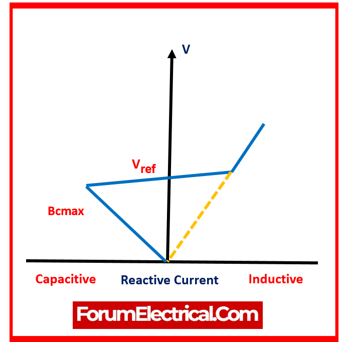
V = Vref + Xs.I (When the susceptance is between the high & low ranges of capacitor & reactor banks.)
V = – (I / Bcmax) for condition (B implies that Bcmax)
V = (I / Bcmax) for condition (B implies that BImax)
Advantages of Static VAR Compensator
- These SVC devices can improve the power transmission capacity of transmission lines.
- The installation of SVCs can help improve the system’s transient strength.
- SVC is commonly used for managing steady states and a wide range of voltages, which is one of its primary advantages.
- SVC boosts the load power rating, which reduces line losses and improves system efficiency.
- Controls both continuous and transitory overvoltage.
- There are no moving parts, therefore less maintenance is required.
Disadvantages of Static VAR Compensator
- Additional equipment is required to implement surge impedance compensation since the equipment lacks revolutionary parts.
- The device is large and heavy.
- Deliberate dynamic response.
- The device is not suited for the regulation of voltage up & down due to furnace loads.
Applications of Static VAR Compensator
- SVCs are widely employed in high-voltage transmission networks and heavy industrial units, where changes in load demand can create voltage instability & other power quality problems.
- They can improve the energy system stability, improve power transmission capabilities, and reduce electrical grid losses.
- SVR is used to adjust for surge impedance as well as to sectionalize large transmission lines.
- Improve and enhance the overall power factor to provide a smooth and reliable power system.

 controls voltage and improves power factor in electrical systems. SVCs stabilize voltage, improve system efficiency, and reduce voltage swings by dynamically injecting (or) absorbing reactive power. This post summarizes the Static VAR Compensator's function in electrical power systems.)