
- Rectifier
- What is Half Wave Rectifier?
- Components of the Half Wave Rectifier
- Working principle of the Half Wave Rectifier
- Rectifier Equivalent Circuit
- Rectification on the Half-Wave Rectifier
- Half-Wave Rectifier (HWR) Operation
- Half Wave Rectifier’s Ripple Factor
- Efficiency of a Half Wave Rectifier
- RMS Value
- Advantages of the Half Wave Rectifier
- Disadvantages of the Half Wave Rectifier
- Applications of the Half Wave Rectifier
- Half Wave Rectifier Vs Full Wave Rectifier
A device that changes direct current (DC) into alternating current (AC) is called a rectifier.
It can be accomplished through the utilisation of a diode (or) a collection of diodes. While half wave rectifiers only make use of a single diode, full wave rectifiers make use of a number of diodes.
Because diodes only permit current to flow in one direction, the operation of a half wave rectifier have advantage of this property of diodes.
Rectifier
The rectifier is the component in an electrical circuit that reverses the flow of alternating current (AC) into direct current (DC). While current can only flow in one way, alternating current often flows in the other direction.
The Rectifier operates according to the principle of the biassing condition of a PN junction diode.
In one direction, the diode has a low resistance to the flow of current, known as being in a forward biased condition.
But, in the opposite direction, known as being in a reverse biased condition, the diode has a high resistance.
Rectification is the process of changing an alternating current (ac) signal into a direct current (dc).
Two distinct types of rectifiers can be distinguished by the configurations of their diodes and the rectification of alternating current (ac) signals to direct current (dc), either the one-half cycle of ac or both half cycles of ac.
They are as follows:
1). Half Wave Rectifier
2). Full Wave Rectifier
The Half Wave Rectifier is described in detail below.
What is Half Wave Rectifier?
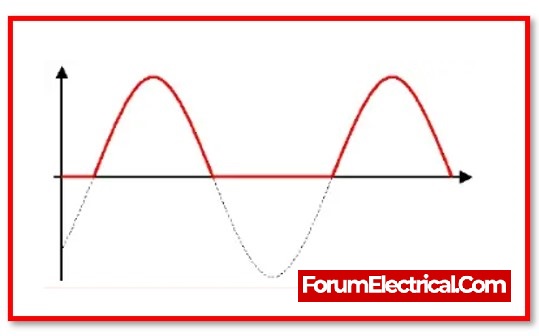
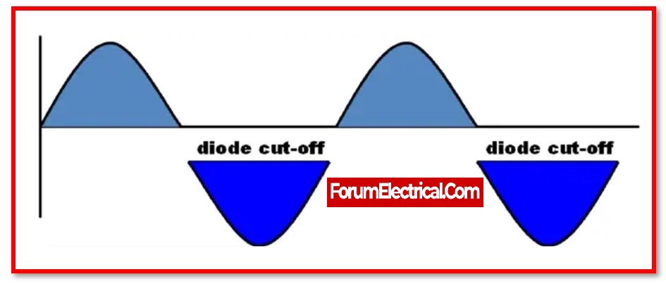
A half wave rectifier is a type of rectifier that changes an alternating current (ac) signal into a direct current (dc) signal by allowing either a positive or negative half cycle of the alternating current (ac) waveform while blocking the other half cycle.
The rectification process in a half-wave rectifier circuit only requires the use of a single diode during the rectification. A basic type of rectifier is known as a half-wave rectifier.
Since a diode will only let current flow in one direction, the operation of a half wave rectifier is predicated on this characteristic of the component.
Hence, it changes the alternating current signal into a direct current signal.
The forward biassing condition is the only one in which a diode will conduct when an alternating current voltage is applied across it. that is, when the cathode side of the diode is negative in comparison to the anode side of the diode.
The efficiency of a half-wave rectifier is lower than the efficiency of a full-wave rectifier. This is due to the condition that a half-wave rectifier only passes half of the input.
The highest efficiency of a half-wave rectifier is around 40.5%, while the efficiency of a full-wave rectifier is approximately twice as high as that of a half-wave rectifier.
The amount of ripple that is generated by a half wave rectifier is greater than that generated by a full wave rectifier.
In order to get rid of the ripple content, more filtering is required. As a result, it is utilised in very infrequent situations.
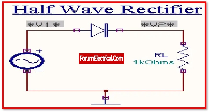
Components of the Half Wave Rectifier
A half-wave rectifier is comprised of three primary parts. They are as follows:
- AC Source
- Transformer
- Resistive Load
- Diode
1). AC Source
All of the components in the circuit receive alternating current from this current source. In most applications, the signal for this alternating current is depicted as a sine wave.
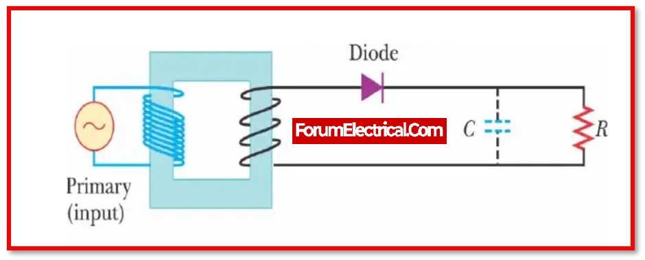
2). Transformer
A transformer is typically used to enhance or reduce the AC voltage. The AC voltage is reduced by a step-down transformer, while the AC voltage is increased from a low to a high level by a step-up transformer.
Given the low voltage needed by a diode, a step-down transformer is typically used in a half-wave rectifier.
Without a transformer, the diode will be destroyed by the excessive AC voltage. While a step-up transformer can be useful in some cases.
The secondary winding in a step-down transformer has less turns than the primary winding. As a result, the voltage in the secondary winding of a step-down transformer is lower than that in the main winding.
3). Resistive Load
This is the equipment that restricts the flow of the electric current only to a predetermined level.
4). Diode
A diode in the half-wave rectifier permits current to flow in only one direction while blocking it in the other.
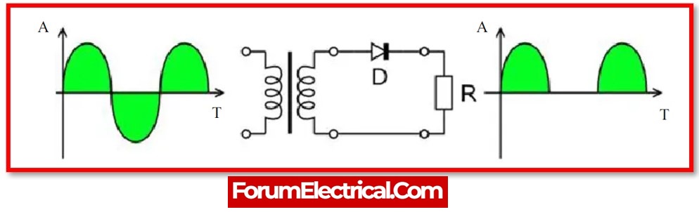
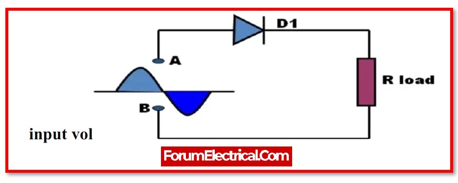
Working principle of the Half Wave Rectifier
The diode is in a condition known as forwarding bias during the positive half cycle, and during this time it is conducting current to RL i.e., Load resistance.
A voltage develops across the load that is identical to the input AC signal during the positive half cycle. This voltage is called the load voltage.
Alternately, the diode will be in a condition known as reverse bias during the negative half cycle.
During this time, there will be no passage of current through the diode. The only voltage that can be seen across the load is the AC input voltage, and this is the outcome that can be obtained when the phase angle is in the positive half cycle.
The DC voltage is characterised by periodic pulsations caused by the output voltage.
Rectifier Equivalent Circuit
Rectifier circuits can be single-phase or multi-phase. Single-phase low – powered rectifier circuits are employed in domestic applications, whereas three-phase rectification is required in industrial HVDC applications.
Rectification, or the process of converting AC to DC, is the most important and essential application of a PN junction diode.
Rectification on the Half-Wave Rectifier
In the single-phase half-wave rectifier, either that the negative or positive half of the alternating current voltage flows, while the other half is blocked. As a result, the output continues to receive only half of the AC wave.
A single diode is required for single-phase half-wave rectification, and three diodes are required for three-phase rectification.
Half-wave rectifiers have more ripple content than the full-wave rectifiers and require much more filtering to eliminate harmonics.
The no-load output DC voltage of an ideal half-wave rectifier for the sinusoidal input voltage is
Vrms = Vpeak / 2
Vdc = Vpeak / ᴨ
Where
Vdc, Vav – Alternating current output output voltage (or) average output voltage
Vpeak – The peak value of the input phase voltage.
Vrms – The root mean square voltage output voltage.
Half-Wave Rectifier (HWR) Operation
Only forward bias conducts PN junction diode. Half-wave rectifiers convert AC to DC like PN junction diodes. A half-wave rectifier circuit connects the load resistance in series with PN junction diode.
Half-wave rectifiers receive AC. A step-down transformer supplies to load resistor and diode.
Half-Wave Rectifier works in two phases:
- Positive half-wave and
- Negative half-wave.
1). Positive Half-Wave
Step-down transformers reduce 60 Hz AC voltage to low voltage. The transformer secondary winding generates a minimum voltage. Secondary winding voltage (Vs). Diode input voltage is small.
As the input voltage reaches the diode, the positive half cycle allows electric current to flow, while the negative half cycle blocks it.
The P-N diode’s forward DC voltage equals the input signal’s positive side.
The P-N diode’s reverse DC voltage and the diode’s negative input signal are the same.
Hence, diodes conduct current when forward-biased and block current when reverse-biased. In an AC circuit, diode current flow during the ‘+’ ve cycle & inhibits it during the -ve cycle. +ve
HWR enables some -ve half-cycles or negative current. Diode minority charge carriers cause this generation.
Minority charge carriers generate little current and can be ignored. The load section cannot monitor this small amount of -ve half cycles.
Practical diodes assume negative current is zero.
The load resistor uses diode-generated DC current. Hence, the resistor is an electrical load resistor that calculates DC voltage/current (RL).
Electric current flows through the circuit’s electrical output. HWR resistors use diode current. This makes it a load resistor.
HWR RLs limit diode-generated DC current.
Hence, a half wave rectifier outputs sinusoidal +ve half-cycles.
2). Negative Half-Wave
Negative half-wave rectifiers work and are built similarly to positive ones. Only the diode direction will change.
Step-down transformers reduce 60 Hz AC voltage to low voltage. Hence, the transformer secondary winding generates little voltage. Secondary voltage is secondary winding voltage (Vs). Diode input voltage is small.
As the input voltage reaches the diode, the diode moves into the forwarding bias and allows electric current to flow during the negative half cycle and into negative bias during the positive half cycle.
The P-N diode’s forward DC voltage matches the diode’s negative input signal. The P-N diode’s reverse DC voltage and positive input signal are the same.
Hence, diodes conduct current when reverse biased and block current when forward biased. In AC circuits, the diode enables current flow during the -ve cycle & blocks it during the +ve cycle. -ve HWR enables some +ve half-cycles or positive current.
Diode minority charge carriers cause this generation.
Minority charge carriers generate little current and can be ignored.
The load section cannot see this small amount of +ve half cycles. Positive current is zero in a practical diode.
The load resistor uses diode-generated DC current. Hence, the resistor is an electrical load resistor that calculates DC voltage/current (RL).
Electric current flows through the circuit’s electrical output. HWR resistors use diode current.
Load resistor describes the resistor. HWR RLs limit diode-generated DC current.
The output section’s +ve& -ve half-cycles are similar in a perfect diode. The +ve& -ve half cycles differ from the input cycles.
Hence, a half-wave rectifier outputs sinusoidal -ve half-cycles. The half-wave rectifier outputs continuous +ve& -ve sine signals, not pure DC signals and pulsing.
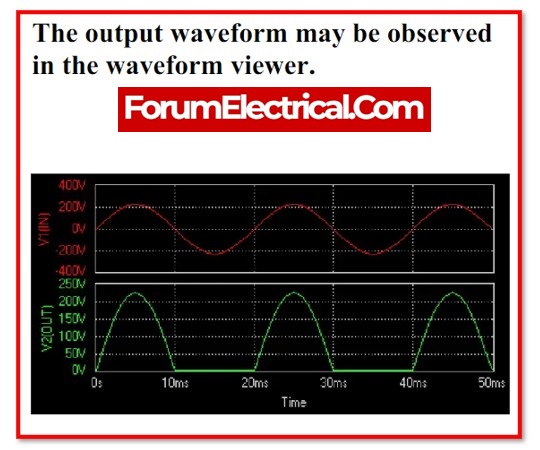
3). HWR Operation Output
The diode conducts current during positive half cycle when the upper end’s secondary winding is positive compared to the lower end.
When the diode’s forward resistance is assumed to be zero, the input voltage is directly applied to load resistance during positive half-cycles. AC input voltage waveforms match output voltage and current waveforms.
When the lower end’s secondary winding is positive compared to upper end, the diode is reverse biased and does not conduct current.
The load voltage and current are zero during the negative half-cycle. The reverse current is neglected due to its low magnitude. During negative half cycle, no power is delivered.
The load resistance produces positive half cycles as output voltage. Filters across the load smooth the output wave, which is a pulsating DC wave.
The input wave is half-cycle, so it’s a half-wave rectifier.
Half Wave Rectifier’s Ripple Factor
The ripple factor is what determines how effectively an AC voltage may be converted into a DC voltage by a half wave rectifier. Users may determine the ripple factor by using the formula
γ=√(Vrms/Vdc)2 -1
1.21 is the value for the ripple factor of the half wave rectifier.
Efficiency of a Half Wave Rectifier
The efficiency of a half wave rectifier can be determined by calculating the ratio of the DC power output to the AC power input. The formula for determining the efficiency of a half-wave rectifier is as follows:
η=Pdc/Pac
The half wave rectifier has an efficiency that can reach a maximum of 40.6%.
RMS Value
The RMS value of the half wave rectifier can be calculated as
RMS = Maximum Value/2
VRMS=VMax/2
Advantages of the Half Wave Rectifier
- Simplified and with a reduced number of component parts.
- A lower overall cost because there is less equipment required other than the probability that there will be an increase in costs over time as a result of increased power losses
Disadvantages of the Half Wave Rectifier
- They only let one half-cycle of each sinewave pass through, so other half-cycle is completely lost. This results in a decrease in power.
- They generate a voltage that is not very high.
- The output current that we get does not consist entirely of DC, and it still has quite a bit of ripple in it (it has a high ripple factor).
Applications of the Half Wave Rectifier
- They are utilised in the demodulation of various signals.
- They are used in applications that require rectification.
- Applications involving signal peaks make use of them.
Half Wave Rectifier Vs Full Wave Rectifier
| S.NO | Half Wave Rectifier | Full Wave Rectifier |
|---|---|---|
| 1 | A half wave rectifier is a rectifier circuit that allows just one half of the applied input signal to pass and blocks the other half. | A rectifier circuit that can pass the whole input signal is referred to as a full wave rectifier. |
| 2 | The nature of the half-wave rectifier is unidirectional. | The full wave rectifier exhibits bidirectional characteristics. |
| 3 | The half-wave rectifier circuit consists of a single diode. | A full-wave rectifier circuit consisting of two or more diodes. |
| 4 | The voltage control of the half wave rectifier is effective. | The voltage regulation of the full wave rectifier is superior than that of the half wave rectifier. |
| 5 | The maximum applied input voltage equals the maximum inverse voltage | The highest inverse voltage is double the greatest input voltage supplied. |
| 6 | Efficiency of the half wave rectifier is around 40.6%. | Approximately 81.2% is the efficiency of the full wave rectifier. |
| 7 | The frequency of the signal that is produced has the same exact values as the frequency of the signal that is received as input. | The frequency of the signal being output is twice as high as the frequency of the signal being supplied. |
| 8 | The half-wave rectifier has a ripple factor of 1.21. | The full-wave rectifier has a ripple factor of 0.482. |
| 9 | The half-wave rectifier has a form factor of 1.57. | A full-wave rectifier has a form factor of 1.11. |
| 10 | The peak factor for a half-wave rectifier is equal to 2. | A full-wave rectifier has a peak factor of 1.414. |