
What is meant by motor solo run test?
The motor solo run test involves operating or spinning the motor without engaging any load with the motor’s own rotor shaft. This is referred to as the motor being tested in “solo run” mode.
All of the motors used in the industries will undergo a “no load test” or “motor solo run” to ensure that they are operating efficiently. No-load testing is the easiest of these methods. The term “no-load” refers to operating a motor at its rated voltage & frequency while having “no load” (i.e., nothing) linked to the shaft. The output current & power are measured, and their acceptance is determined by comparing them to limitations set from “master motors.” The measurement of
- Vibration,
- Rotational speed, and
- Direction
is another significant external check.
This is beyond the scope of the test because the motor is factory tested at the workshop of the manufacturer.
Objective of Solo Run Test
The primary objective of this method is to confirm the following;
- To verify through functional testing that all parts and equipment work, regulate, and operate in line with authorized design documentation.
- To ensure that the motor is fitted correctly and full fills the requirements for the intended service when it is in use.
- To give baseline information for evaluations of AC motors to be performed in the future.
Solo Run Test Equipment
- Multi-meter
- Clamp-on Ammeter
- Stopwatch
- Insulation Resistance Tester
- Noise meter
- Surface Pyrometer or other appropriate thermometer (Automatic measurement equipment should be utilized when it is available.)
- Tachometer
Pre-Requisites
- Make sure that all overload devices, circuit breakers, fuses, starters, and other components have been appropriately sized, installed, and tested before carrying out this test.
- The control circuit of motor completed a functional test.
- Verify that the switchgear’s START and STOP pushbuttons, which energize and de-energize the contactor, respectively;
- Verify whether the contactor is also driven by the remote control circuits for start and stop.
- Verify that the contactor is de-energized by all motor protection relays.
- During the execution of this test, communication between the control & monitoring areas must be established.
Procedure of Motor Solo Run Test
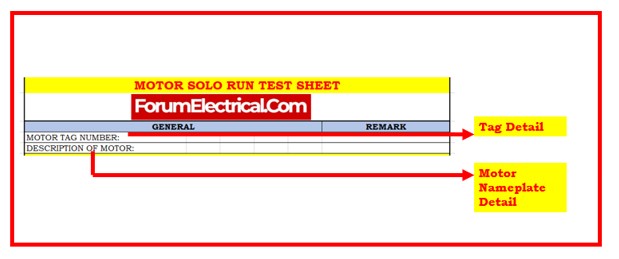
- Nameplate information and tag number is typically located on all manufactured electric motors. Understanding the information on nameplates can be difficult at times, however it is essential. It is required to include all information of the motor’s nameplate and tag number.
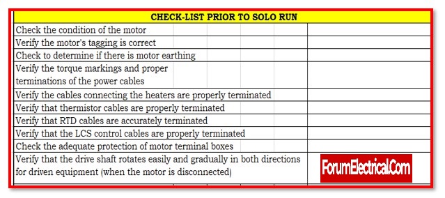
- Make sure the motor is securely fastened by checking the foundation.
- Check the motor’s grounding via visual inspection.
- If it is impossible to separate the motor from the equipment it drives, write this in the remarks area and explain why & how the motor was tested.
- Examine the motor’s lubrication via sight inspection or record check.
- Examine the shaft’s flexibility in rotation by manually rotating it if possible. Notify any odd noises or drag effects.
- Check to determine if the bearing-cooling water system is functioning properly, if applicable.
- Check for circuit continuity at the motor termination on a motor with a terminal strip (such as a MOV).
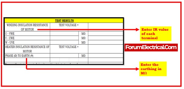
- Determine the resistance of the feeder and motor windings.
- When the motor is de-energized, check to see if the space heater (if equipped) is powered.
- Turn on the motor and make sure everything is working properly. For a total of few hours, let the motor run. If the motor vibrates or gets too hot during the test, check it out.
- Keep track of the voltage and current readings.
- Any irregularities that could endanger the motor during the motor no-load test must be terminated.
- Gather and evaluate the necessary attachment data.
- Any strange sounds or physical modifications should be recorded during operational testing in the data sheet’s observations.
- Stop the motor.
- Restore back the state of the motor control circuits before the test.
Common acronyms used in checklist
- LCS – Local Control Station
- CW – Clockwise
- ACW – Anti-Clockwise
- IR – Insulation Resistance
Limitations and Precautions
- The correct controlling mechanism (starter, switch, or breaker) must be attached to the motor before it may be used.
- When conducting tests, applicable program tagging guidelines must be followed.
- Do not “MEGGER” equipment that contains solid-state components.
- AC motors should be perfectly prepared to start electrically, mechanically, & instrumentally.
The significance of insulation testing
The insulation resistance tester, often known as a megohmmeter or Megger, can provide important details on the state of the motor insulation. The recommended procedure in the manufacturing sector is to do periodic tests & record the results so that undesirable developments can be found and fixed to stop an outage and protracted downtime.
For already-in-use equipment, the test could be non-destructive, or it may be prolonged at a high voltage to completely destroy prototypes. Utilizing the Megger involves some learning curve. To prevent damaging the equipment (or) electrocuting the operator (or) fellow workers, the proper settings, connection techniques, test durations, and safety measures must be put into effect.
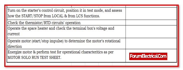
Checklist
The checklist for the Motor’s Solo run test sheet has been attached below: