 and the power-switching mechanism it performs in an efficient way. Using this simple guide, you will learn how this electrical device easily switches between several power sources, providing that there is no interruption in electricity during power outages.)

- What is an Automatic Transfer Switch (ATS)?
- Working Principle of an Automatic Transfer Switch
- Circuit Diagram of an Automatic Transfer Switch
- Working
- 4 Steps to Install Automatic Transfer Switch
- What are the available arrangements for ATS?
- How an Automatic Transfer Switch detects a Power Loss?
- What is the capacity of ATS?
- Various ATS Transition Types
- ATS – Modes of Operation
- Different Automatic Transfer Switch Types
- Advantages of Automatic Transfer Switch
- Disadvantages of Automatic Transfer Switch
- Applications of Automatic Transfer Switch
- Difference Between Automatic Transfer Switch & Static Transfer Switch
- Automatic Transfer Switch Vs Static Transfer Switch
- Ratings
- What does an Automatic Transfer Switch (ATS) do in a UPS System?
- Why do we need an Automatic Transfer Switch?
- How does an Automatic Transfer Switch work?
A transfer switch is a device that switches an electrical load between two power sources, such as main and backup.
These switches enable the secure connection or separation of various power sources from an electric load.
However, it is essential to correctly separate power sources when they are not in use and to ensure that changes from a single source of power to another are carried out in a secure and regulated manner.
Transfer switches are classified into two types:
- Manual &
- Automated.
An operator operates manual switches, but automatic switches work automatically if one of the power sources is gaining or losing power.
As a result, this article provides an overview of one form of automatic transfer switch, or ATS.
What is an Automatic Transfer Switch (ATS)?
Low-voltage automated transfer switch assemblies provide a dependable method of shifting critical load connections between primary & backup power sources. When their normal (primary) power supply fails, data centers, hospitals, factories, and a variety of other facility types that require constant or near-continuous uptime typically use an emergency (alternative) power source that includes a generator or a backup utility feed.
When there is a power outage in the primary electrical system, this switch activates a backup power source, such as a UPS or uninterruptible power supply.
When the automatic transfer switch is linked to both the primary and backup power sources, it serves as an electrical relay, acting as a bridge between the equipment and the power supply.
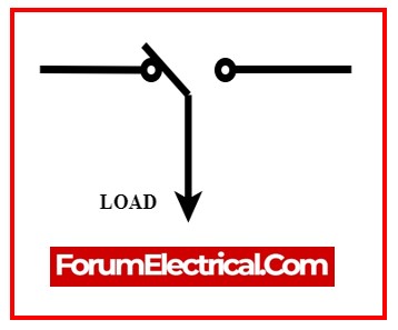
The symbol for an automatic transfer switch is illustrated below.
A typical transfer sequence consists of:
- The standard power source for utilities fails.
- When electricity from the generator or backup utility supply is steady and within specified voltage and frequency tolerances, the transfer switch moves the load to the emergency power source. The transfer procedure can be manually started or self-acting, depending on the requirements and preferences of a facility.
- The transfer switch facilitates the transfer of load between the emergency power source to the regular power source upon restoration of utility power. Either manually or automatically, the retransfer process is started.
Working Principle of an Automatic Transfer Switch
An automatic transfer switch works by automatically switching electrical energy between primary and backup power sources without human intervention.
This switch is a necessary part of an EPSS (emergency power supply system).
These switches are made up of
- Relays and
- Solid-State Devices
that have been mounted to check and control the input voltage. If the input supply is steady and above a certain level, this switch acts as a monitor.
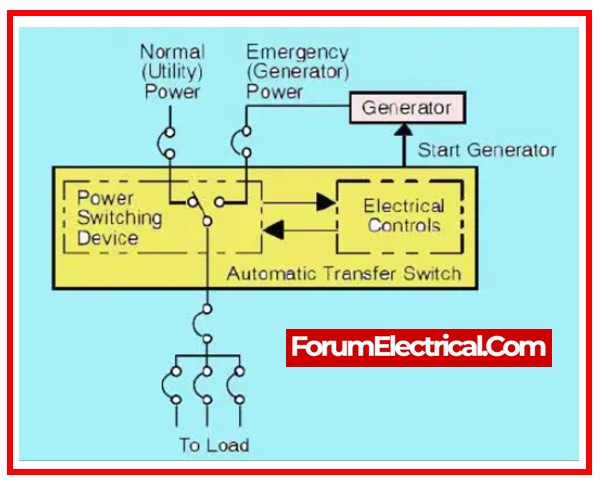
When the voltage dips, a solid-state relay device detects it and generates a signal to start the generator.
An ATS switch is essential for connecting the backup generator to the house. In general, electricity flows from the utility to the house’s main electrical system, where it powers all of your circuits.
This switch functions as the brain of the entire electrical system. Once this switch is connected, they will be able to switch between utility and generator power automatically.
When this switch detects a power outage at home, it sends generator power to the house, and then detects the electricity when it is restored and returns utility power to the house.
Circuit Diagram of an Automatic Transfer Switch
The wiring diagram for a single-phase power generator’s automatic transfer switch is illustrated below. This wiring diagram is simple and inexpensive. This wiring requires
- Magnetic Contactor,
- 2 MCB,
- Line Cables (L1, L2), and
- Wiring Control.
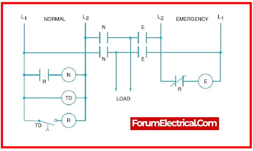
Working
The current flow toward the contactor and coil contactor will turn on once the public utility power source is turned on.
Following that, the NC connection will be unplugged and the NO terminal will be connected, supplying energy from the utility to the load at house.
The energy flow towards the coil contractor will be turned off whenever the public utility power goes out, preventing the contractor from working. The NC terminal will then reconnect, & the NO terminal will be disconnected once more.
Upon activation of the magnetic contactor, the NC terminal is immediately connected. Power from the generator flows through the NC terminal, providing electricity to the household load.
All that this automatic transfer switch (ATS) does is switch the power between generators or between a public utility supply and a power generator.
4 Steps to Install Automatic Transfer Switch
The procedure for installing an ATS outlined below provides general instructions. Different automated transfer switch companies may specify different steps for the ATS devices. Always read the manufacturer’s instructions thoroughly before commencing the installation process.
Step 1: Locate the Automatic Transfer Switch
The first step is to select a suitable position for the automatic transfer switch (ATS), particularly if we are building one for generator backup. It should be near the main breaker panel & easily accessible so that one can respond swiftly in the case of an emergency.
While installing a solar transfer switch, place it adjacent to the solar inverter. Make sure the switch is located at a suitable height & away from anything that might damage it.
Most transfer switch instructions specify a distance of 18 from the center of the service panel. However, this may vary according to the installation conditions.
Step 2: Wiring Automatic Transfer Switch
The next step is to connect the automated transfer switch. This might be a sensitive process because when working with electrical cables and high voltages. If not confident with doing so, need to contact a professional electrician.
Typically, the main power source is wired to the “Line” terminals on the ATS, and the load is wired to the “Load” terminals. The backup power is subsequently connected to the “terminals”. An auto transfer switch is usually pre-wired, so all have to do is connect the wires to the appropriate connectors.
Step 3: Connect the Automatic Transfer Switch
Following that, install the switch. Manufacturers’ user manuals generally provide instructions for connecting automated transfer switch modules. Make sure to follow these instructions while installing ATS.
Make sure to understand the mounting process. Different transfer switches provide various installation options. Some will also require an enclosure, although others, particularly the solar transfer switch, might be plugged in.
Step 4: Testing the Automatic Transfer Switch
After installed the ATS, should test it to ensure that it works properly. It can be accomplished by first turning on all of the lights & appliances in the residence or company, and then activating the ATS.
If everything is functioning properly, the lights & appliances must remain operational even if the power goes out. Note that the transfer switch installation should be completed correctly, or it will be unsafe.
The majority of solar transfer switches are simple to install and may only take a few steps to get up and running. A solar ATS switch can be plugged into a utility outlet, inverter, or load circuit.
What are the available arrangements for ATS?
There are numerous configurations that make use of two and three power sources.
Two Power Sources
- Utility – Generator
- Utility – Utility
- Generator – Generator
Utility – Generator
A generator and an electric utility service are included in the usual transfer switch setup for backup and regular power sources. Usually, this configuration is called an emergency stand-by generator system.
It’s possible that multiple engine-generator sets are running in parallel with the one generator.
Utility – Utility
In order provide backup in the distribution system and enable prompt restoration of service to the load in the occurrence of an upstream equipment failure, this use case makes use of two utility sources.
The two sources can come from one electric service that is transmitted through redundant directions within the facility, or they may originate from two independent sources, in which case the public utility would need to supply two electric services.
Generator – Generator
Sometimes, especially in remote sites, transfer switches are used to provide prime power between two generator sets. Under such circumstances, the generator could need to run nonstop, around-the-clock.
Source power is frequently switched across the generator sets such that runtime is distributed equally between them.
Three Power Sources
- Utility – Generator – Generator
- Utility – Utility – Generator
Utility – Generator – Generator
When a critical facility has an emergency standby generator system installed, it is common for them to have provisions for the second generator connection.
This second generator can be utilized as a redundant emergency backup during bad weather or when the first generator is undergoing planned maintenance.
There are conditions when the first generator is placed on-site permanently while the second is a roll-up, portable generator that is used as needed.
Utility – Utility – Generator
This technique provides an emergency backup generator source and increases the redundancy offered by a dual utility’s installation.
How an Automatic Transfer Switch detects a Power Loss?
The automatic transfer switch uses both incoming & outgoing line monitoring to identify a power outage. A voltage sensor that monitors the incoming line determines whether the system is receiving enough voltage to function safely.
An alert will sound & the automatic transfer switch (ATS) will start to turn on the backup generator if there is not enough electricity.
A frequency sensor keeps focus on the outgoing line to determine whether the device is emitting enough frequency for safe operation. An alert will sound & the automatic transfer switch (ATS) will start to switch to the standby generator if there is insufficient frequency.
What is the capacity of ATS?
Diesel generators are equipped with automatic transfer switches that are constructed to fulfill continuous current ratings ranging from 30 to 4000 amperes on average.
Generally, the ampere ratings that are utilized the most frequently are as follows: 30, 40, 70, 80, 100, 150, 225, 260, 400, 600, 800, 1000, 1200, 1600, 2000, 3000, and 4000 amperes among others.
Various ATS Transition Types
Transfer switches with
- Open Transition switch loads and
- Closed Transition switch loads
between normal & emergency power sources.
The specific activities provided by a given load, as well as the significance of those functions to safety (or) security, function as an important part in establishing which type of transition is necessary.
Open Transition
A break-before-make transfer is known as an open transition. Before connecting to the other power source, the transfer switch disconnects from the first one. Open-delayed and open-in-phase are examples of open transitions.
Closed Transition
A make-before-break transfer is known as a closed transition. Before disconnecting the connection with the primary power source, the transfer switch connects to a secondary power source. Because there is never a pause between disconnecting and reconnecting, power is continuously transmitted to downstream loads.
ATS – Modes of Operation
| Manual | Both the initiation and execution of transfers are done manually; usually, this involves pushing a button (or) turning a handle. Local initiation takes place. |
| Non-Automatic | To electrically execute the switching mechanism, manually initiate a transfer by turning a switch or pressing a button on an internal electromechanical device. Initiation can take place locally or remotely. |
| Automatic | The transfer switch controller (TSC) is self-acting & fully controlling both initiation and operation. The automatic controller initiates the switch when it detects a loss of source power or unavailability, and the switching mechanism then operates as a result. |
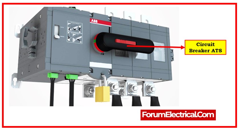
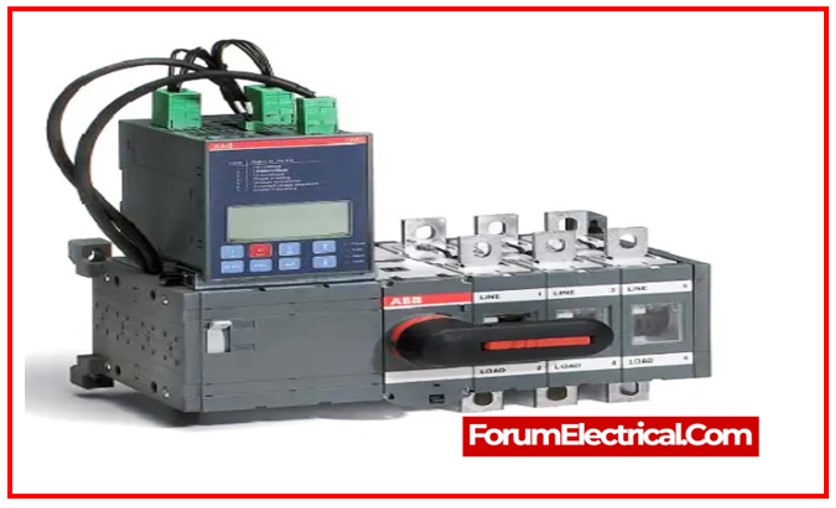
Different Automatic Transfer Switch Types
- Compact ATS,
- Circuit Breaker ATS (CB ATS), and
- Contactor ATS
are the three types of automatic transfer switches that are accessible
Compact ATS
Compact ATS often referred to as a change-over switch, the small automated transfer switch breaks currents that are present in short circuits. Because they require fewer components to be connected, new automated transfer switches offer a high level of reliability while cutting down on the amount of time needed for device setup within the panel. These are typically the most expensive switches to purchase.
Circuit Breaker ATS
Short circuit currents are created, broken, and sustained by the CB automatic transfer switches. Usually, an installer connects a number of ACBs or MCCBs to these switches. It is necessary to employ these accessories inside the circuit. Single breaker may be closed at any period with this type of switch because it primarily has two interlocked CBs. These switches are costly than contactor ATS.
Contactor ATS
Short-circuit currents can be created and sustained by this type of automatic transfer switch, but they cannot be broken. These switches frequently depend on 3- or 4-pole low-voltage contactors. The ATS contactor type features an electrically powered and mechanically seized design. It operates at a much faster speed and reduces transfer time as compared to circuit breakers. These are typically the most cost-effective switches.

Advantages of Automatic Transfer Switch
- This switch’s primary advantage is that it immediately transfers the load’s electricity to the generator.
- This switch has sensors built into it to detect variations in the voltage and frequency of the primary source of power.
- These switches are equipped with a time delay mechanism designed to protect the electric circuits and the generating device from power fluctuations.
- These switches are easy to use, safe, and dependable.
- These switches are necessary to ensure a steady flow of electricity.
- These switches are perfect for effortlessly switching to generator power.
Disadvantages of Automatic Transfer Switch
- This switch’s primary disadvantage is that many establishments will experience a large error margin.
- Compared to manual switches, these kinds of switches are more costly.
- When it comes to maintenance, these switches need more attention than manual switches.
Applications of Automatic Transfer Switch
- ATS switches are used to protect telecommunications and data networks, industrial processes, and essential installations such as financial transaction centers and health care facilities.
- These switches are utilized for transferring power between 2 power sources, such as the major utility and the secondary backup power source.
- These switches are also utilized in various types of electrical switching applications such as utility-to-utility, generator-to-generator, and three-source systems.
- ATS is utilized in hospitals, medical buildings, schools, shopping malls, restaurants, shopping malls, warehouses, and industries, among other places.
Difference Between Automatic Transfer Switch & Static Transfer Switch
Automatic Transfer Switch Vs Static Transfer Switch
| Automatic Transfer Switch (ATS) | Static Transfer Switch (STS) |
|---|---|
| An automated transfer switch is a self-contained, intelligent power switching device. | A static transfer switch is a component of permanent switching equipment that is fixed and automatic. |
| An ATS automatically switches to a backup power source when it detects an electrical outage in the primary source. | STS operates by continuously transmitting important loads between two AC power sources. |
| ATS switches come in two different types: circuit breaker and contactor. | STS switches are offered in two configurations: single phase and three-phase. |
| Throughout the transfer, ATS has a small millisecond(ms) break inside supply. | Throughout the transition, STS has no interruption in supply. |
Ratings
To maintain system integrity and dependability, consider the withstand closing current rating (WCR) while using a transfer switch in a power distribution system. The UL1008 standard allows for the marking of transfer switches with one (or) more short-circuit (or) short-time WCRs specific to an overcurrent protection device type. Multiple-rating transfer switches provide application versatility.
Other standard rating of ATS is:
- NFPA 110: The National Fire Protection Association’s standard addresses emergency and standby power systems, as well as the requirements for automated transfer switches in these systems.
- IEC 60947-6: An International Electrotechnical Commission standard that specifies the specifications for low-voltage switchgear & control gear, includes automatic transfer switching equipment.
What does an Automatic Transfer Switch (ATS) do in a UPS System?
Automatic Transfer Switches (ATS) are frequently employed for providing resilience for small uninterruptible power sources (less than 10 kVA) that cannot operate in parallel.
Why do we need an Automatic Transfer Switch?
An Automatic Transfer Switch (ATS) is an essential component in electrical systems that automatically switches power supply from a particular source to another in the case of a power outage or disruption. The purpose we need an ATS are:
Continuous Power Supply
An ATS provides continuous power to key loads that include essential equipment, appliances, or systems by seamlessly transitioning between primary & backup power sources.
Reliability
By regulating the transfer process, an ATS lowers the need for manual intervention throughout power transitions, lowering the risk of human mistake and assuring dependable power transmission.
Faster Response
ATSs can detect power outages & switch power sources in milliseconds, enabling faster reaction times than manual transfer techniques. This prompt response helps to reduce downtime and maintain the continuity of operations in essential applications.
Protection
The device’s current-carrying parts are all enclosed, making protection from direct contact. There are no exposed wires. In an emergency that necessitates manual operation, the automatic & remote functions are disabled by simply operating the lever (handle).
Safety
ATSs have safety mechanisms to prevent back-feeding & connect only one power source at a time. This reduces the danger of electrical risks and harm to equipment or workers.
Space Reducing
The device was designed to be exceedingly small and compact, as well as totally contained. Compared to standard equipment, the Compact ATS occupies up extremely little cabin room. There is no need for any further equipment, including an external power supply.
Versatility
ATSs can be configured to support a variety of power sources such as utility mains, generators, and alternative energy systems like as solar or wind power, making them adaptable solutions for a numerous range of applications.
Scalability
ATSs can be implemented into both small and large-scale electrical systems, enabling scalability & flexibility to meet the unique requirements of each installation.
Compliance
In many jurisdictions, regulatory standards and rules demand the installation of ATSs in specific applications, including commercial buildings, healthcare facilities, data centers, & industrial plants, to assure safety and reliability compliance.
In general, an Automatic Transfer Switch is critical for maintaining a constant power supply, improving system reliability, assuring safety, & meeting regulatory requirements in a variety of applications.
How does an Automatic Transfer Switch work?
ATS is an auto operate, power switching equipment which is operated under a specific control logic. The main function of an ATS is to supply electric power from any of the two power sources to the connected load circuit which is in most cases electrical appliances ; lightings, motors, computers, etc.
The control logic or the automatic controller is usually microprocessor based and is always on the look out for electrical parameters, voltage and or frequency of primary as well as the alternate power sources. This works on the basis that, when the connected power source collapses, the ATS is supposed to switch (transfer) the load circuit to the other power source, if available. In most of the automatic transfer switches design, the machine defaults to connect to the primary source (utility) and only connects to the alternate source (engine-generator, backup utility) if called upon to do so through either the primary source being faulty or through orders from the operator.