
- What is Earthing?
- How is Earthing done?
- Earthing System Components
- Earthing Procedure
- Step-by-Step Procedure for Earthing Installation Process
- Step-1: Site Evaluation and Preparation
- Step-2: Earthing Electrode Selection
- Step-3: Installation of Electrodes
- Step-4: Jointing and Joining
- Step-5: Verification & Testing
- Step-6: Documentation & Maintenance
- Step-7: Certification & Compliance
- Types of Earthing
- Types of Electrical Earthing
- What are the 5 IEC types of Earthing Systems?
- What are the 5 Earthing Systems?
- Importance of Earthing
- Difference between Earthing and Neutral
- Earthing vs Neutral
- Advantages of Earthing
- Disadvantages Of Earthing
- Applications of Earthing
- Frequently Asked Questions (FAQ)
- 1). What are the 4 types of Earthing?
- 2). What is the principle of Electrical Earthing?
- 3). What are three main reasons for Earthing?
- 4). What is the method of Electrical Earthing?
- 5). Why is salt used in Earthing?
Earthing is the process of directly transmitting and discharging electrical energy to the ground via a low resistance wire. An electric discharge is the release and transfer of electrical energy in an applied electric field using gas as a medium.
Electric discharge occurs when electrons are rapidly transferred from one to another. It generates visible sparks. Lightning is the most common & observable electric discharge phenomenon. These electric discharges may lead to large problems and a large number of accidents.
Earthing is a method of preventing electric shock. It protects us by acting as a protective conductor during a fault current flowing to the earth. Earthing also causes a protection device, such as a circuit breaker or a fuse, to cut off the electric current to the faulty circuit.
This post discusses the importance, procedures, and advantages of earthing in protecting electrical systems & preventing risks.
What is Earthing?
Earthing is the method of transmitting the immediate discharge of electrical energy straight to the ground via a low resistance wire. Electrical earthing is accomplished by connecting a non-current carrying component of the equipment or the supply system’s neutral to the ground. It is also called electrical earthing.
Galvanized iron is commonly used for earthing. The earthing provides a simple path for the leakage current. The equipment’s short circuit current flows to the earth, which has no potential. As a result, the system & equipment are protected from damage.

How is Earthing done?
Earthing can be done to ensure safety through connecting the electrical device to earthing systems (or) electrodes positioned near the soil or below ground level.
The electrode (or) earthing mat is put beneath the ground level and is fitted with a flat iron riser. It facilitates in connecting all of the equipment’s non-current-carrying metallic elements.
When an overload current is sent through the equipment or a fault occurs in the system as a result of the current, the fault current passes through the earthing system. The earth mat conductors help increase the voltage value equivalent to the earth mat resistance increased by a ground fault and protect the device from overload current (or) fault current.
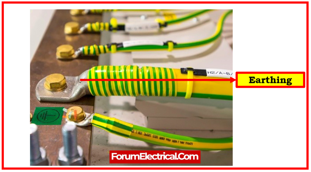
There should be 3 types of wiring in every house: live, neutral, & earth. The ground is connected to the buried metal plate via the live and neutral conductors that transport electric current from power station. While in use, electric appliances such as refrigerators, iron boxes, & televisions are connected to the earth wire. As a result, these electronic devices get protection from surges or faulty power supplies. Local earthing is performed near the house’s electrical meter.
Earthing System Components
The materials utilized in an earthing system will differ significantly depending on the ground’s resistivity:
- Earth electrodes
- Earth pits
- Permanent and mechanical earth bonds
- Conductivity enhancers (or) Conductivity boosters
1). Earth Electrodes
To reduce resistance, a ring (or) mesh of bare, buried horizontal conductors is commonly used, augmented by vertical electrodes.
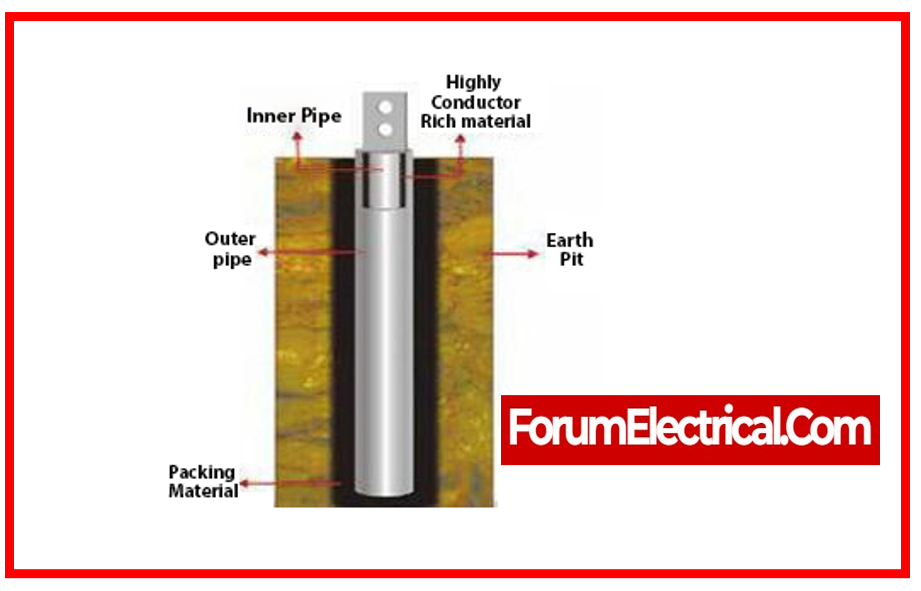
2). Earth Pits
Earth pits are typically located on the exterior of structures. Their purpose is to serve as an accessible manhole for testing and inspections.
The earth pit is connected at the bottom of an excavation by a device that allows the earth conductors to be disconnected and must bear an earth sign.
3). Permanent and Mechanical Earth Bonds
To make the connections required to implement an earthing (or) grounding system, a welding procedure that assures these connections can last for the whole service life of the installation is recommended.
Aluminothermic welding is the consequence of a chemical reaction that produces the molecular bonding of two (or) more metallic conductors. This molecular bonding outperforms any mechanical bonding in terms of mechanical, electrical, and corrosion properties.
Furthermore, the tablet format & remote electronic initiator kit generate much more efficient outcomes, saving money and increasing safety.
4). Conductivity Enhancers (or) Conductivity Boosters
Conductivity enhancers are used to keep soil moisture and deliver ions that greatly lower resistance in a long-lasting & corrosion-free way in soils with high resistivity, where reaching a low earth resistance value can be unattainable even with many electrodes.
Earthing Procedure
Step-by-Step Procedure for Earthing Installation Process
Step-1: Site Evaluation and Preparation
Determine appropriate locations for the earthing electrodes based on soil type, moisture content, & proximity to the electrical system.
Remove any obstacles or debris to make electrode placement easier.
Step-2: Earthing Electrode Selection
Based on soil conditions, available space, and desired resistance, choose suitable electrodes (rods, plates, pipes).
Determine the number & size of electrodes required to obtain the desired resistance value.
Step-3: Installation of Electrodes
Excavate an earthing trench of sufficient depth & diameter for the selected electrode.
Insert the electrodes vertically (or) horizontally into the pit, maintaining adequate contact with the surrounding dirt.
Use conductors (copper strips or wires) to connect the electrodes, ensuring secure & corrosion-resistant couplings to setup installation.
Step-4: Jointing and Joining
For robust and long-lasting connections between conductors and electrodes, utilize exothermic welding (or) compression connectors.
Connect the earthing system to electrical system, being sure to use low-resistance connections.
Step-5: Verification & Testing
Use specialized tools to determine the resistance of the established earthing system during earth resistance testing.
Check the connections for continuity test and integrity to ensure a dependable & consistent path for the fault currents.
Step-6: Documentation & Maintenance
Maintain thorough documentation outlining the installation procedure, test findings, and earthing system requirements.
Inspect the earthing system on a regular basis for corrosion, damage, (or) degradation, & undertake maintenance as needed to ensure its efficiency.
Step-7: Certification & Compliance
Verify that the installed earthing system complies with applicable standards, ordinances, and laws.
Types of Earthing
Earthing, also known as electrical grounding, is used in the construction of buildings, wiring, & electrical devices.
Different materials are used for grounding, which results in different types of earthing systems. In order to attain efficient electrical grounding, various earthing materials necessitate different configurations and methods.
The following are the different types of electric earthing systems:
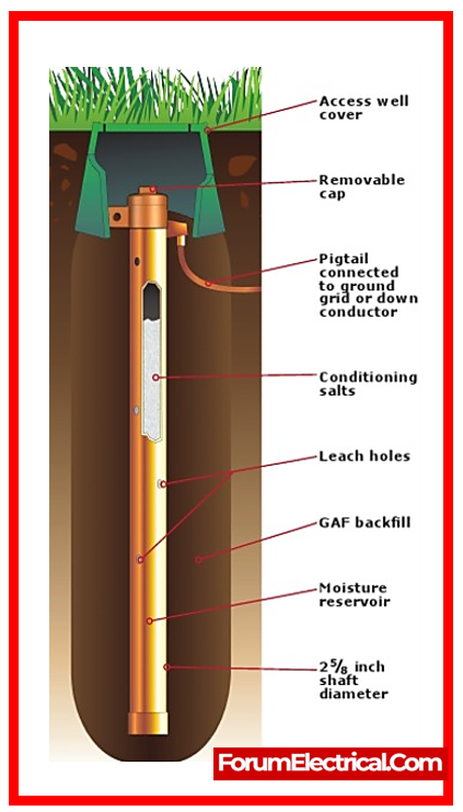
1). Pipe Earthing
2). Plate Earthing
3). Strip Earthing
4). Rod Earthing
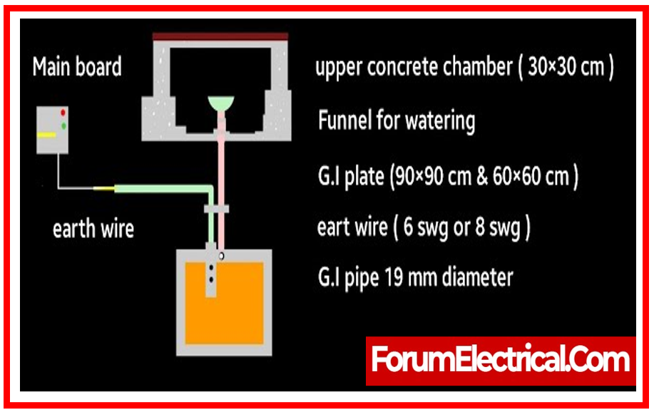
1). Pipe Earthing
Connecting to the electrical conductors of the earth using a steel pipe is a standard procedure known as pipe earthing. For pipe earthing, a galvanized steel pipe measuring 2 meters in length and 38 mm in diameter is put vertically in ground to serve as an earth electrode.
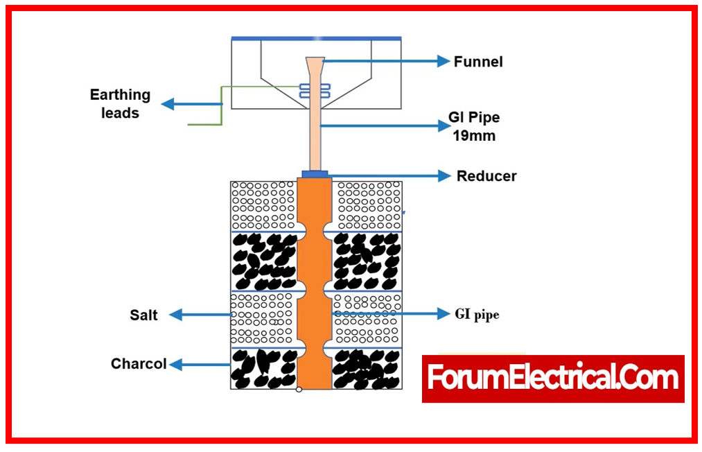
How much iron pipe is required is dependent on the soil’s moisture level & the strength of the stream. Installing the steel pipe to a maximum depth is dependent on the moisture content of the soil.
When it comes to earthing, pipe earthing is the best, most cost-effective, and simplest option.
2). Plate Earthing
A copper (or) galvanized iron plate is inserted vertically into the ground hole (ground pit) at a height of less than three meters for this earthing method. Keeping the soil around the plate earthing system moist makes for a more efficient electrical grounding system.
In order to change the direction of the earth’s electric charge, this plate is connected to wires.
3). Strip Earthing
This method of earthing involves digging horizontal trenches and planting strip electrodes with minimum depth of 0.5 m and a cross-sectional size of 6.0 mm2. Galvanized iron or steel electrodes must have a cross-sectional area of at least 25 mm x 1.6 mm.
An earth resistance of at least 15 meters would be sufficient for a conductor to be buried.
4). Rod Earthing
To obtain the desired earthing resistance, a galvanized steel pipe and copper rod are driven vertically down the ground using a hammer or manual methods. The electrodes’ lengths lower the earth’s resistance.
This is accomplished by firmly redirecting the short-circuit voltage to the earth by burying the rod in the dirt at a specific depth.
This method of earthing is inexpensive and works well in sandy regions.
On the other end, in highly resistive soils, they are not as effective as plate earthing or other earthing methodologies.
Types of Electrical Earthing
There are two primary components of the electrical equipment that do not conduct current.
These components do not affect the electrical equipment’s system or frame.
Two different types of electrical earthing can be distinguished based on the earthing of the two non-current carrying components.
1). Neutral Earthing
2). Equipment Earthing
1). Neutral Earthing
With the use of the GI wire, neutral earthing connects the system’s neutral to earth directly.
Earthing in a neutral state is also known as system earthing. Systems with star winding are the most common users of this form of earthing.
Equipment like generators, transformers, motors, etc., have neutral earthing integrated inside.
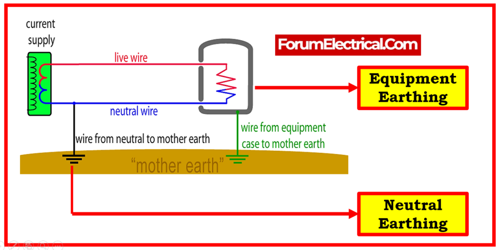
2). Equipment Earthing
Electrical equipment receives this form of earthing.
The equipment’s metallic frame and other parts that do not carry electricity are grounded to the earth through the conducting wire.
In the case of a malfunction, the current can be safely routed to ground through the wire. As a result, protect the system.
NOTE:
- Earthing is a method of preventing electric shock.
- There are three types of wiring in a house: live, neutral, and earth.
- The earth mat conductors contribute to the maintenance of an equal voltage value.
- The earthing strips are useful in transmission.
- Earthing protects us by acting as a conductor.
What are the 5 IEC types of Earthing Systems?
IEC 60364 specifies that all power systems are classified into one of five earthing types:
- TN-S,
- TN-C-S,
- TN-C,
- TT, and
- IT.
These are the categories that cover all power systems.
What are the 5 Earthing Systems?
TN-S, TN-C-S, TT, TN-C, & IT are the five different types of earthing systems that are listed in BS 7671.
Where,
Earth, which is derived from the French word “terre”
N = Neutral
S = Separate
C = Combined
I = Isolated
The source of an IT system is either connected to earth by means of a purposefully introduced earthing impedance or it is isolated from the source of the earth.
Importance of Earthing
Here are some reasons why earthing is absolutely necessary:
- The earthing system prevents the employees from being electrocuted by a short circuit.
- In case that insulation fails, earthing remains the most direct path for short circuit electricity to be transmitted.
- Earthing prevents lightning strikes and high voltage surges that could harm equipment and people.
- In the case of an electrical fault, high voltage flows across electric circuits, causing damage to the electrical installation. Excessive voltage goes through the earth if earthing is done.
Earthing involves electrically connecting installation items to electrical cables or electrodes near the soil or below ground level. The flat iron riser of the earthing mat (or) electrode beneath the ground connects all non-current-carrying metallic equipment pieces.
The fault current from the equipment goes via the earthing system to earth to protect it. When the fault occurs, the earth mat conductors increases the voltage equivalent to its resistance times a ground fault.
The contacting assembly is earthing. The metallic conductors connecting installation objects to earthing are referred to as electrical connections. Earthing and connection form the earthing system.
Difference between Earthing and Neutral
Earthing vs Neutral
| Earthing | Neutral |
| Earthing involves connecting certain electrical power system components to the ground via low-resistance cable for safety. | Normal current flows through an AC circuit neutral. The load is balanced. |
| Normal current does not flow through it. | The charge is constantly present. |
| Earthing cannot be changed into neutral and vice versa. | It is possible to transform neutral into earthing. |
| The execution of it can either come from a neutral line (or) be carried out independently. | It originates from the line that is neutral. |
Advantages of Earthing
- Earthing is the best and safest approach to prevent electrocution in a building.
- There is no potential for change on earth, thus it is regarded as neutral. By connecting low-level devices to the ground with low-resistance cable, balancing is achieved.
- Since metal, when properly earthed, will not transfer current, its conductivity is not a problem when using it in electrical systems.
- Equipment and users are safe from harm in the event of an overload or sudden voltage spike, provided adequate earthing measures are implemented.
- It lessens the likelihood that the present leaking could cause fire dangers.
Disadvantages Of Earthing
- The earthing process is associated with high costs.
- There is a potential risk to one’s safety during earthing.
Applications of Earthing
- Low voltage system utilization appliances are accessible to household users where suitable electrical earthing is performed to protect the electrical appliances as well as ourselves from electric shocks.
- Voltage fluctuations are the most common cause of faults for residential customers. Proper electrical earthing is essential during voltage changes.
- The primary purpose of the earthing system in high voltage systems (>1kv) is less on safety and more on the reliability of the power supply and equipment protection. The L-G fault is the most prevalent form of defect in a high voltage system. The fault current pass through the earth is closed during the L-G fault.
Frequently Asked Questions (FAQ)
1). What are the 4 types of Earthing?
Some of the most frequent types of earthing are as follows:
- Plate Earthing
- Pipe Earthing
- Rod Earthing
- Strip Earthing
2). What is the principle of Electrical Earthing?
The earthing principle is an essential concept in electrical systems that assures safety, dependability, and protection from electrical problems. Earthing creates a controlled path for the fault current to pass through harmlessly by connecting an electrical installation to the earth.
3). What are three main reasons for Earthing?
- Ensures that electrical equipment and devices are safe from high electric current.
- Helps in the direct flow of electric current within the earth.
- Protects the electric appliance from damage and it prevents building collapse due to lightning.
4). What is the method of Electrical Earthing?
Earthing methods include pipe earthing, plate earthing, rod earthing, wire or strip earthing, and earthing through water mains. The most prevalent earthing methods are pipe earthing & plate earthing.
5). Why is salt used in Earthing?
It is possible for the conductivity of the conductor to decrease due to corrosion that occurs on the wire at the ground end. We add some salt to the mixture in order to boost the conductivity, which will allow the charge from top to more easily penetrate the earth.