
1). What are the clearances required for 33kV Installations?
The minimum clearances for 33kV installations are as follows:
Phase to phase distance: 350 mm.
Phase to ground distances: 3200 mm (outdoor), 2500 mm (inside).
Vertical clearance from ground to lowest conductor: 6.1 meters (in outdoor installations).
2). What are the Protection Systems used for Transformers in a plant?
Typical transformer protections include:
Overcurrent Protection: Protects against excessive currents.
Differential Protection: Detects internal defects in transformers.
Buchholz Relay: Prevents internal gas collection and oil leaks.
Over-temperature Protection: Detects and responds to transformer winding overheating.
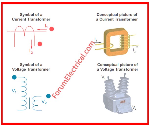
3). What are CTs and PTs? Where and why are they used?
- A CT (Current Transformer) measures current by scaling down high currents to a quantifiable range. Typically utilized in protection & metering circuits.
- PT (Potential Transformer) reduces high voltage to a safe level for metering & protection applications.
Both are utilized in switchyards, substations, & control panels to ensure the safety and protection of high-voltage equipment.
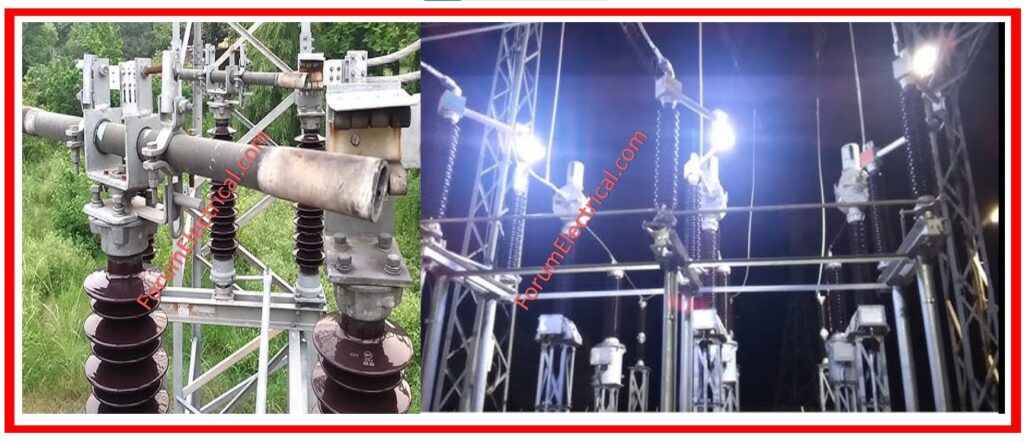
4). How to operate and maintain a Switchyard?
Switchyard maintenance includes:
- Regular checks of breakers, isolators, & busbars.
- Clean and tighten electrical connectors.
- Checking the protective relays for appropriate operation.
- Lubricating mechanical components and inspecting for physical deterioration.
- Ensure adequate grounding of switchyard components.
5). What are the clearances required for a Switchyard?
The necessary clearances for switchyards vary depending on the voltage level:
33kV: requires a minimum of 3200 mm of phase-to-ground clearance.
66kV: 4100 mm phase-to-ground clearance.
400kV: 8.0m phase-to-ground clearance. These clearances contribute to safety & prevent flashovers among live components.
6). What is the significance of Earthing?
Earthing provides a low-resistance conduit for fault currents to safely drain into the ground, shielding equipment and humans from electric shocks and damage. It also helps to keep voltage levels stable.
7). What are the specifications of an Earth pit?
Earth pits normally measure at least 600 mm × 600 mm.
Earth electrodes are made of copper (or) galvanized iron.
Backfill is a mixture of bentonite (or) salt used to minimize resistance.
A pit cover is a detachable cover used for evaluation.
Earth resistance must be less than 1Ω for essential installations.
8). How much should the earth resistance be for a switchyard?
The earth resistance for a switchyard should be less than 1Ω(ohm), with 0.5Ω(ohm) (or) less preferred for improved grounding and safety performance.
9). How to attend a defect on an isolator?
To address an isolator defect:
Step-1: De-energize the circuit.
Step-2: Visually evaluate for mechanical damage or misalignment.
Step-3: Look for loose connections (or) broken contacts.
Step-4: Clean and lubricate the moving parts.
Step-5: Replace any broken components, such as insulators (or) contacts, as needed.
10). What steps should be taken if the isolator contacts & corona ring melt?
If there is melting,
Step-1: Immediately isolate & de-energize the isolator.
Step-2: Examine the level of damage to the contacts & corona ring.
Step-3: Replace melted components with replacement ones.
Step-4: Check for and resolve any potential problems, such as overheating, poor contact, (or) electrical overload.
11). What is the Bay width? How much is needed for a 400 kV substation?
Within a switchyard, the bay width refers to the amount of area that is specifically designated for the equipment.
The normal bay width for a 400 kV substation is practically between 18 and 24 meters, but this might vary based on the layout & the equipment that is being utilized.
12). What is the Line-to-Line clearance on a 400 kV line?
The minimum clearance between phase conductors for a 400 kV transmission line is usually 4200 mm (4.2 meters), depending on the design and climatic factors.
13). What is a Soak pit? Why is it required?
A soak pit is a pit that allows wastewater (or) excess fluids to seep into the ground, typically after passing through a bed of gravel or sand. It is essential in installations with excessive precipitation (or) transformer oil leakage to prevent surface accumulation.
14). What are the sizes required for earth flat and its ratings?
Common sizes for earth flats are:
Copper: Copper measures 25 mm x 3 mm to 50 mm x 6 mm.
Galvanized Iron (GI): Galvanized Iron (GI) measures 50 mm x 6 mm. The size is determined by the fault current rating, which is normally rated to carry up to 25 kA for 1 second.
15). What is the use of a Neutral Grounding Resistor (NGR)?
A Neutral Grounding Resistor (NGR) is used to control fault current during a ground fault in electrical system, shielding transformers and generators from large fault currents that could damage equipment and degrade system stability.
16). What is the purpose of plant earthing?
- Plant earthing prevents electric shocks and ensures personnel safety.
- Maintain voltage stability in the presence of lightning or a failure.
- Protect the equipment against harm caused by ground faults (or) surges.
17). Explain Touch Potential and Step Potential
Touch Potential: The electrical potential between the body part touching an energized object and the ground that a person is standing on while touching the energized object.
Step Potential: The voltage at two points on the ground, separated by the step length while there is a fault. Both can result into electric shock and are major dangers in substations that must be controlled at all costs.
18). How do you choose cables & breakers for a 500 kW HT motor?
Cable Selection: Consider the motor load (500kW), voltage level, allowed voltage loss, and current rating.
For 500kW at 11kV, the cable size is estimated to be around 3-core 70mm².
Breaker Selection: Based on the motor’s full-load current, choose a breaker with a rated current of 50-60A & short-circuit breaking capacity greater than the fault current at the installation location.
19). What are the slip ring motor starting methods?
Slip ring motors can be started with:
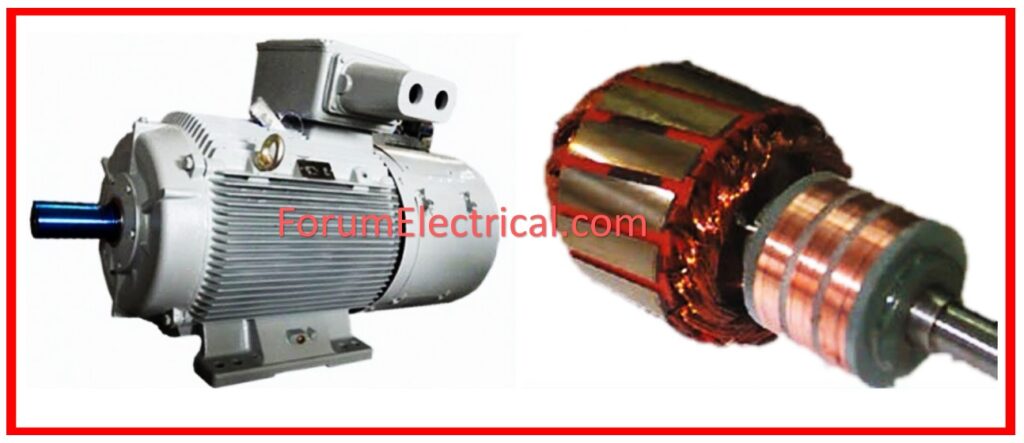
Rotor Resistance Starter: Increases resistance in the rotor circuit to reduce starting current & increase torque.
Auto-Transformer Starter: Lowers the applied voltage during starting.
Soft Starter: Soft starters provide a regulated ramp-up of voltage & current during motor starting.
20). Define a single-line diagram (SLD)
A Single-Line Diagram (SLD) is a simplified illustration of an electrical power system that uses single lines and standard symbols to show the arrangement of electrical components & their connections, providing an overview of the system’s structure.
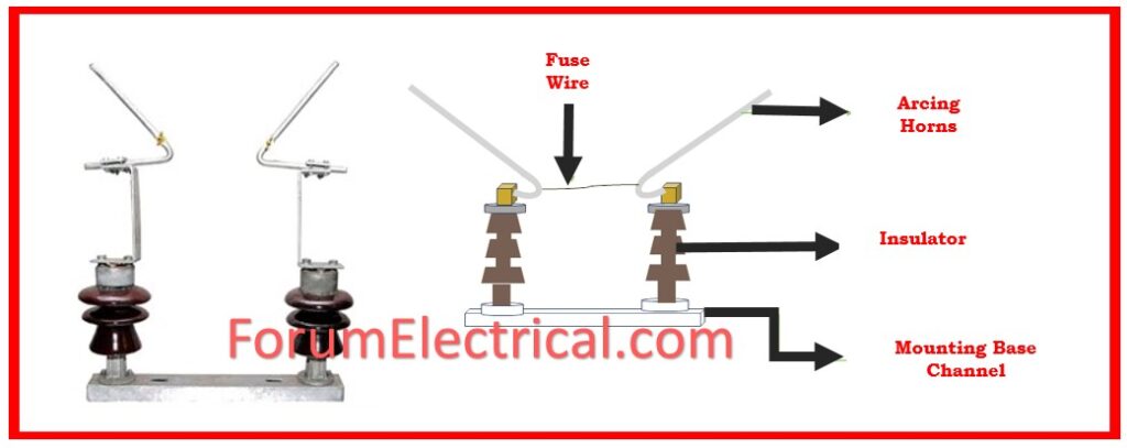
21). What is the Horn Gap for a 33kV HG fuse?
The horn gap for a 33kV HG fuse is usually adjusted between 100 and 150 mm. The gap distance is intended to allow an arc to safely extinguish under fault conditions.
22). What is the lightning arrester rating for 11kV, 440V, & 220kV systems?
- 11kV: 11kV arrester with a 9kV rating.
- 440V: 0.5kV to 1kV rated arrestor.
- 220kV: 198kV rated arrester.
These arresters protect the equipment against overvoltage caused by lightning strikes (or) switching surges.
23). How do you choose a starting method for motors with power greater than 100kW?
Starting methods for motors above 100kW include:
These methods help to reduce inrush current during motor starting.
24). What makes electrical system preventive maintenance important?
Electrical system reliability and safety depend on preventive maintenance. Transformers, switchgear, & motors are inspected, cleaned, and tested regularly to detect wear, corrosion, and malfunction.
This reduces unexpected failures, downtime, equipment lifespan, and safety standards.
Preventive maintenance requires proper documentation and scheduling.
25). How do you enforce electrical safety on-site?
Compliance is ensured by following relevant standards like AS/NZS 3000 (Wiring Rules) (or) the National Electrical Code (NEC), conducting regular safety audits & inspections, utilizing lockout/tagout procedures during maintenance, training all personnel in safety protocols, and providing proper PPE.
Electrical supervisors must enforce grounding and bonding regulations.


 for Preventive Maintenance of Earth Pit")
