
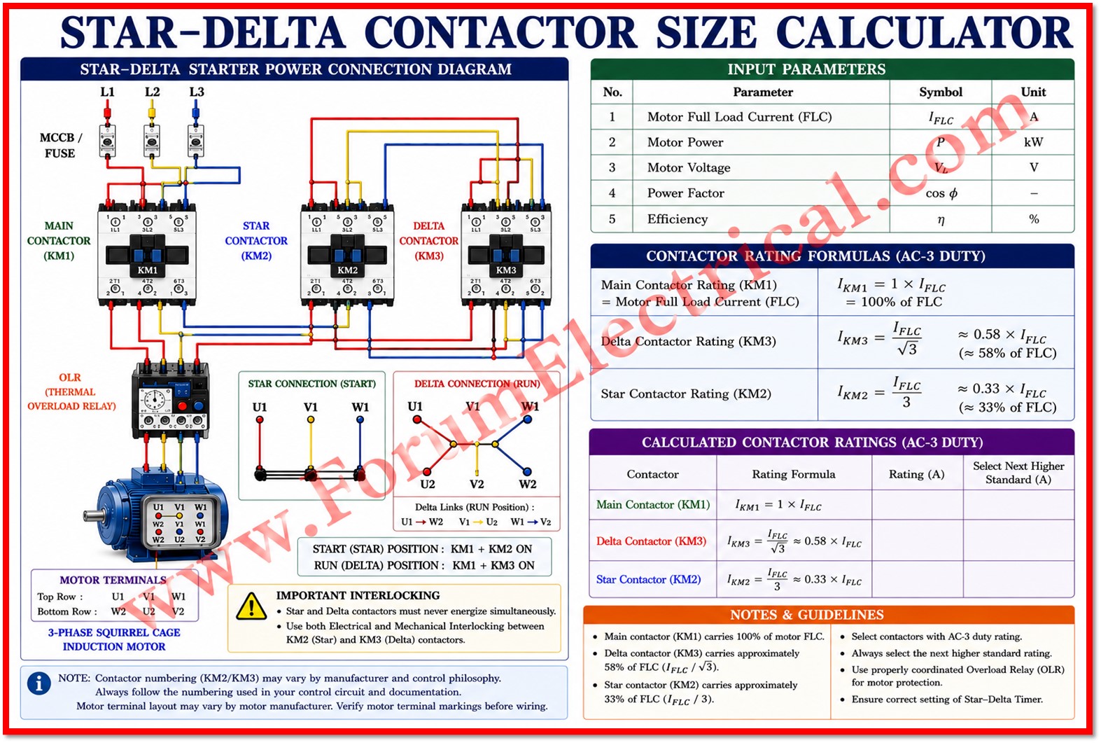
The Star Delta Contactor Size Calculator is an online calculator tool designed to assist electrical engineers and industrial technicians in selecting the correct contactor ratings for star-delta motor starter configurations.
Calculator
Star Delta Contactor Size Calculator
Calculate optimal contactor ratings per IEC 60947-4-1 AC-3 standard for star-delta motor starters
Click here for more Electrical Calculators
You can also follow us on Facebook and Linkedin to receive daily updates.
Related Electrical Calculators
Related Electrical Calculators
All Categories
Electrical Converters
Electrical Machines Calculators
Transformer Calculators
Power Systems Calculators
Battery Calculators
Electrical Engineering Excel Calculators
Unit Converters
The calculator implements industry accepted sizing rules based on the IEC 60947-4-1 AC-3 standard which governs low voltage (LV) switchgear and control gear for motor control applications.
Star-delta starters are widely used across industrial facilities to reduce the high inrush current drawn by squirrel cage induction motors during startup.
By first connecting the motor windings in a star (Y) configuration & then switching to a delta configuration once the motor approaches rated speed the starting current is reduced to approximately 1/3rd of the direct-on-line (DOL) starting current.
Proper contactor sizing is important for reliable and safe operation.
Undersized contactors are prone to premature contact wear, excessive heat buildup and nuisance tripping while oversized contactors increase material costs unnecessarily.
This calculator calculates current ratings and recommends conventional IEC contactor sizes with a 25% safety margin, avoiding error.
How Star-Delta Starting Works?
Three-Phase Starting Sequence
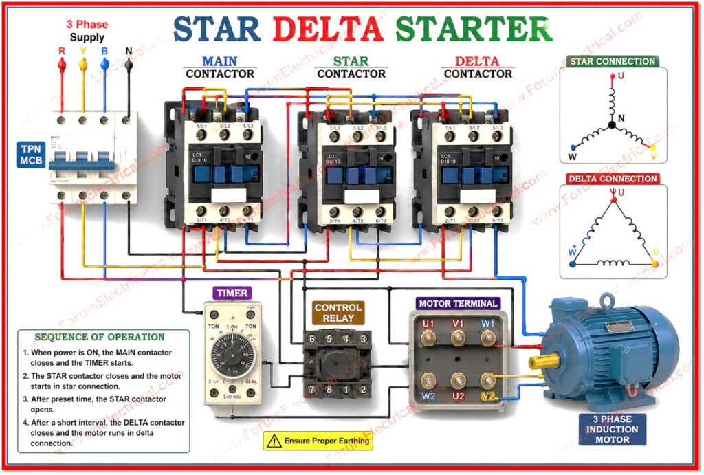
A star-delta starter operates in 3 different phases.
Phase 1: Star Connection
The main contactor and star contactor energise simultaneously.
Motor windings are connected in star that is reducing the voltage across each winding to 1/√3 (approximately 58%) of line voltage.
Starting current is reduced to around 33% of the DOL value.
Phase 2: Transition
After a timed delay (typically 3 to 10 seconds) the star contactor de-energises.
A detailed open transition period follows before the delta contactor closes.
This transition should be rapid to avoid high transient currents.
Phase 3: Delta Connection
The main contactor and delta contactor remain energised.
Motor windings are now connected across full line voltage and the motor delivers its rated output.
Full load current flows continuously through the main and delta contactors.
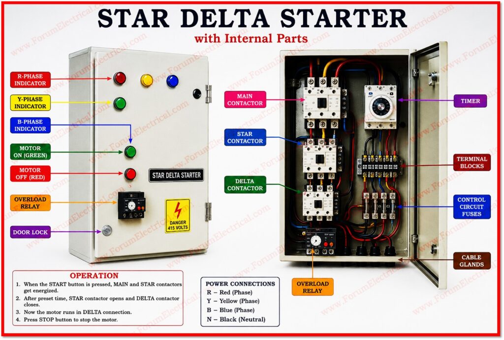
Current Distribution in the Starter
Understanding how current divides across the three contactors is essential for correct sizing.
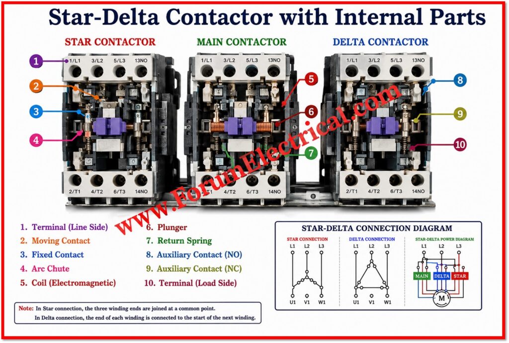
In a star-delta starter 3 contactors carry different portions of the motor current at different times
| Contactor | Active During | Current Rule | % of FLC |
|---|---|---|---|
| Main Contactor | Star + Delta Phases | 1.0 x FLC | 100% |
| Delta Contactor | Delta Phase Only | 0.58 x FLC | 58% |
| Star Contactor | Star Phase Only | 0.33 x FLC | 33% |
Note: The star contactor carries only 1/3 of FLC because the star phase is detail (3-10 seconds) and thermally lightly loaded. The delta contactor carries approximately 58% because it handles the phase winding current in delta connection which equals FLC /√3.
Calculator Inputs
Motor Parameters
| Input Field | Unit | Description |
|---|---|---|
| Motor Power | kW (or) HP | Rated shaft output power. The tool converts HP to kW automatically using the factor 1 HP = 0.746 kW. |
| Supply Voltage | V (3-phase) | Line-to-line voltage of the three-phase supply. Common values: 380V, 415V, 440V, 480V. |
| Motor Efficiency | % | Ratio of mechanical output to electrical input. Typically 80 -92% for standard induction motors. Default: 85%. |
| Power Factor (cos φ) | Dimensionless | Ratio of real to apparent power. Typically 0.75 to 0.95. Default: 0.85. |
Contactor Selections
The user chooses a contactor rating from a dropdown for each of the 3 contactors.
Available standard IEC AC-3 ratings are: 9A, 12A, 18A, 25A, 32A, 40A, 50A, 63A, 80A, 95A, 125A, 150A, 175A, 200A, 225A and 250A.
After calculation the tool use to compare the selected values against the calculated recommendations and raises warnings if any contactor is undersized.
Calculation Methodology
Full Load Current Formula
The Full Load Current (FLC) is calculated using the standard three phase power formula
FLC = (P x 1000) ÷ (√3 x V x cosφ x η)
Where
P – Motor power in kW
V – Line voltage in volts
cosφ – Power factor
η – Efficiency as a decimal (0.85 for 85%)
Contactor Sizing with Safety Margin
After computing or calculating FLC the tool applies the industry standard sizing ratios and then adds a 25% safety margin to consider for
- Motor overloads,
- Supply voltage fluctuations and
- Aging of contacts.
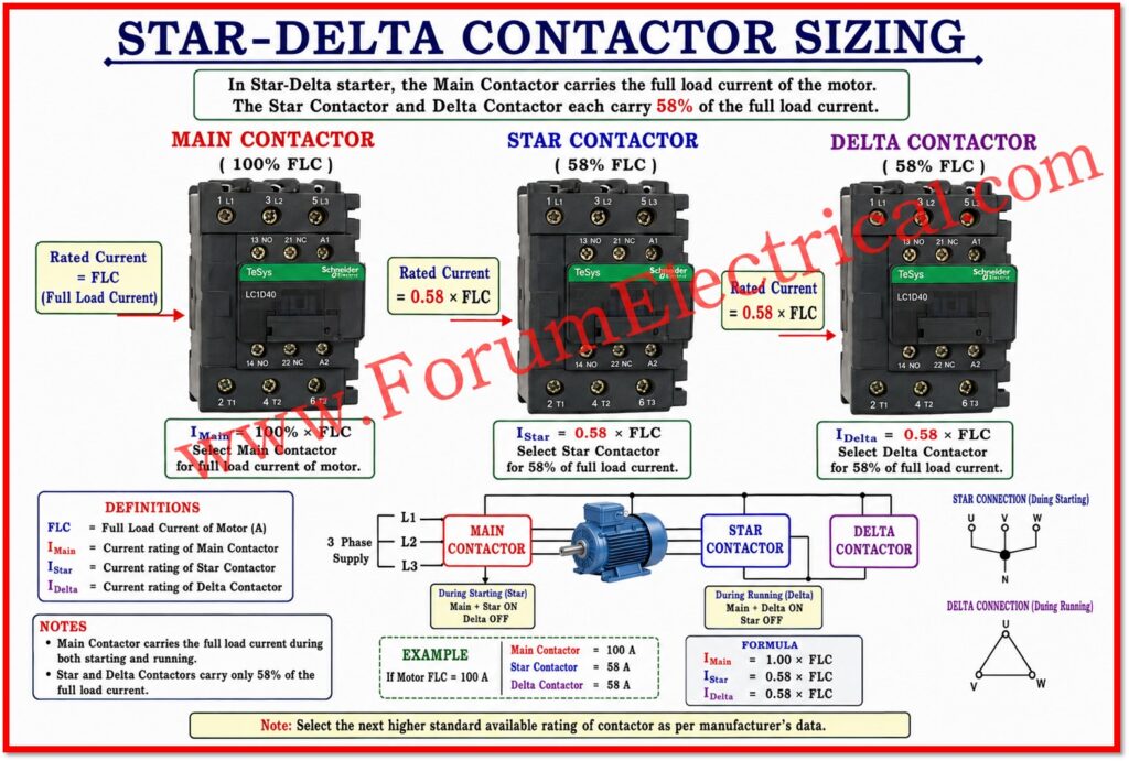
- Star Contactor minimum rating = FLC x 0.33 x 1.25
- Delta Contactor minimum rating = FLC x 0.58 x 1.25
- Main Contactor minimum rating = FLC x 1.00 x 1.25
The online tool then selects the next available standard IEC contactor size that meets (or) exceeds the computed minimum.
Solved Example
A 37 kW, 415V, 3 phase induction motor with efficiency 88% and power factor 0.87 is to be started using a star-delta starter. Determine the required contactor ratings.
Step 1: Calculate FLC
FLC = (37 x 1000) ÷ (√3 x 415 x 0.87 x 0.88) = 67.0 A
Step 2: Apply Sizing Rules
- Star: 67.0 x 0.33 = 22.1 A → with 25% margin: 27.6 A → Select 32A contactor
- Delta: 67.0 x 0.58 = 38.9 A → with 25% margin: 48.6 A → Select 50A contactor
- Main: 67.0 x 1.00 = 67.0 A → with 25% margin: 83.8 A → Select 95A contactor
Output & Warnings
After clicking Calculate, the results panel displays the computed FLC and individual current requirements for each contactor, recommended standard sizes and a comparison against the user selected sizes.
A green confirmation message is shown when all selections comply.
An amber warning is shown for each undersized contactor specifying the required rating and the recommended replacement.
The Engineering Notes section below the results explains the formulas used, the rationale for each sizing percentage and the star-delta sequence in plain language making the tool useful for both experienced engineers and apprentices learning motor control systems.
Applicable Standards
IEC 60947-4-1: Low-voltage switchgear & controlgear; Part 4-1: Contactors & motor starters.
IEC 60034-1: Rotating electrical machines – Rating & performance.
AS/NZS 60947-4-1: Australian adoption of IEC 60947-4-1.
NEMA ICS 2: Industrial Control and Systems – Controllers, Contactors and Overload Relays (for North American reference).