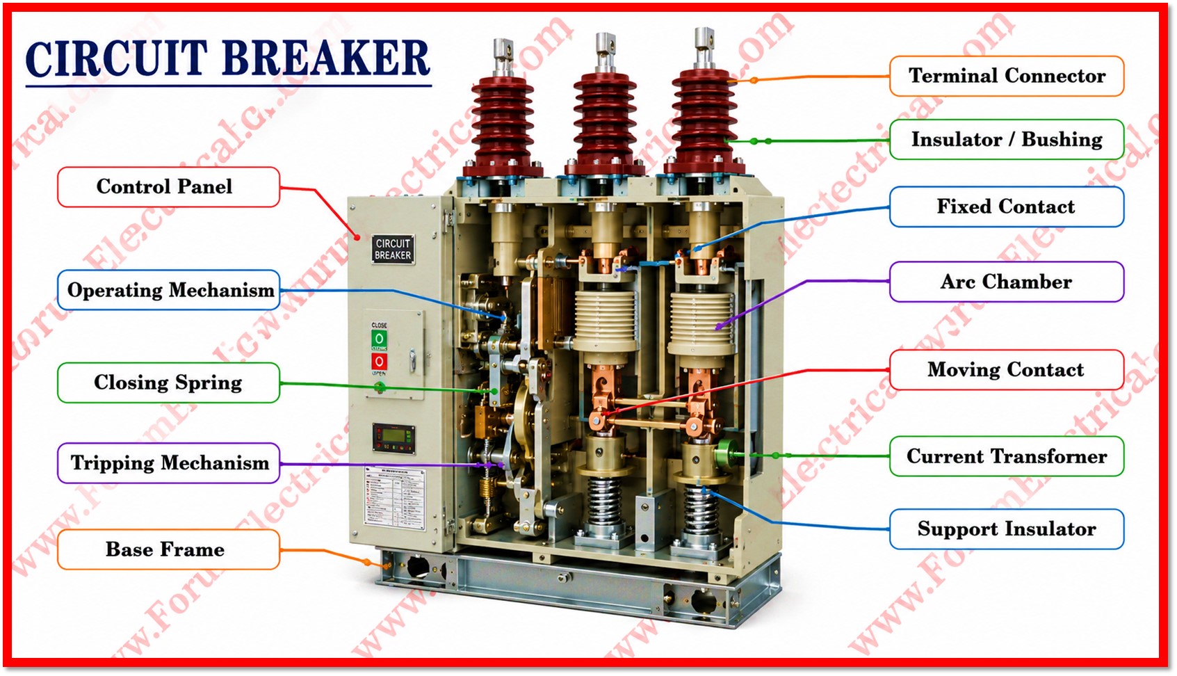
Sizing a circuit breaker correctly is one of the most important calculator in electrical design.
Calculator
NEC Circuit Breaker Sizing Calculator
Based on NEC 210.19(A), 215.2(A) & 240.6(A) standard ratings
Choose whether you already know the load current, or want it derived from power, voltage & power factor.
NEC 210.19(A)/215.2(A): continuous loads require conductors & overcurrent devices sized at 125% of FLA.
Enter a factor below 1.00 if ambient temperature or conductor bundling (NEC 310.15) reduces allowable ampacity.
Results
This tool provides a preliminary estimate only, per NEC 240.6(A) standard ampere ratings. Always verify final conductor ampacity, terminations, and breaker selection against the full NEC (210.19, 215.2, 240.4, 310.15) and local amendments, and have designs reviewed by a licensed electrical engineer.
Related Electrical Calculators
Related Electrical Calculators
All Categories
Electrical Converters
Electrical Machines Calculators
Transformer Calculators
Power Systems Calculators
Battery Calculators
Electrical Engineering Excel Calculators
Unit Converters
Click here for more Electrical Calculators
You can also follow us on Facebook and Linkedin to receive daily updates.
An undersized breaker trips under normal load while an oversized breaker fails to protect conductors from
1). Overheating and
2). Potential fire hazard.
The NEC Circuit Breaker Sizing Calculator is a lightweight, browser based tool built to help electricians, engineers and students quickly estimate a standard breaker rating that complies with the National Electrical Code (NEC).
It draws on 3 key code sections:
- 210.19(A) for branch circuits,
- 215.2(A) for feeders and
- 240.6(A) for standard ampere ratings
to make the user from a loads electrical characteristics to a recommended breaker size in a few seconds.
How the Calculator Works?
The tool accepts either a directly measured load current (full-load amps or FLA) (or) a load power rating in kilowatts and it derives the current automatically when power is supplied.
The user also specifies
- System voltage,
- Number of phases,
- Load type and
- Derating factor and
the calculator returns 4 values:
- Full load current,
- Minimum ampacity,
- Ampacity after any derating adjustment and
- Standard breaker size.
1). Determining Full-Load Current
If the user already knows the FLA it is entered directly.
Otherwise, when power is provided the calculator converts kilowatts to watts and applies the standard single phase (or) three phase current formulas, incorporating the entered power factor.
For 3 phase systems the calculation divides power by the square root of three multiplied by voltage and power factor for single-phase systems it divides power by voltage & power factor.
2). Applying the Continuous Load Multiplier
Per NEC 210.19(A) & 215.2(A) any load expected to operate continuously for 3 hours (or) more must have its conductors and overcurrent protection sized at 125 % of the full load current (FLC).
The calculator applies this multiplier automatically whenever the user selects continuous load while non continuous loads pass through at 100 % of FLA.
3). Adjusting for Derating
- Ambient temperature and
- Conductor bundling
can reduce a conductors allowable ampacity under NEC 310.15.
The calculator lets the user enter a derating factor between 0.1 and 1.0 dividing the minimum required ampacity by this factor yields the adjusted ampacity that the final breaker size should meet (or) exceed.
4). Standard Size
NEC 240.6(A) lists the standard ampere ratings manufacturers generate for
- Fuses and
- Circuit breakers.
which is the code-compliant approach to breaker selection.
Key Inputs Parameters
| Field | Purpose |
| Input Method | Choose between entering current directly or calculating it from power |
| Load Power (kW) / Current (A) | Base electrical value for the load being protected |
| System Voltage | Nominal system voltage, from 120 V to 480 V |
| Number of Phases | Single-phase or three-phase system |
| Power Factor | Used only when deriving current from power |
| Load Type | Continuous (125% multiplier) or non-continuous |
| Derating Factor | Reduction for ambient temperature or conductor bundling |
Solved Example
Given
Consider a 240 V, single phase continuous load rated at 6.5 kW with a power factor of 0.95.
Solution
The calculator first converts power to watts (6,500 W) and divides by voltage multiplied by power factor (240 x 0.95) yielding a full-load current of roughly 28.5 A. Because the load is continuous, the 125 percent multiplier applies, generating a minimum required ampacity of about 35.7 A.
If no derating is entered, the adjusted ampacity remains 35.7 A, and the tool scans the NEC 240.6(A) list of standard ratings until it finds the first value at or above that figure, 40 A that becomes the recommended breaker size.
If the same circuit instead ran through a conduit bundled with several other current-carrying conductors, an ambient derating factor of, say, 0.8 might apply. Dividing 35.7 A by 0.8 raises the adjusted ampacity to roughly 44.6 A, which pushes the recommended breaker up to the next standard size of 50 A.
Answer
This example illustrates how a single derating adjustment can change the final recommendation by a full step, underscoring why the ambient and bundling conditions of an installation should never be overlooked.
Typical Use
- Quick field checks that sizing a branch circuit for a new appliance (or) motor load.
- Preliminary feeder sizing during early stage design prior to a full load study is complete.
- Teaching tool for students learning how continuous load multipliers & derating factors interact
- Cross checking a proposed breaker size prior to submitting drawings for review
Summary
By combining a simple current derivation step the mandatory 125 % continuous load multiplier, an optional derating adjustment and NEC 240.6(A) standard sizing the calculator condenses a multi step manual process into a single and transparent result.

