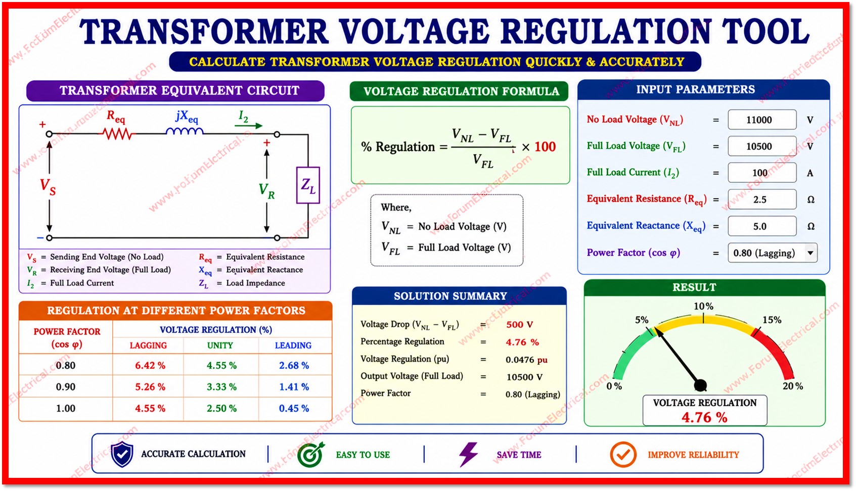
The Transformer Voltage Regulation Tool is an online calculator tool designed to compute transformer voltage regulation in accordance with IEEE standards.
Transformer Voltage Regulation Calculator
Transformer Voltage Regulation Calculator
IEEE-standard · Single & Three Phase · Approximate & Exact Phasor Methods
Used only to display the turns ratio
Rated secondary (no-load) voltage
Primary + secondary resistance referred to secondary side
Primary + secondary leakage reactance referred to secondary side
If only %Z is known, enter %Z below and leave %X blank
Between 0 (exclusive) and 1 (inclusive)
Actual load as % of rated kVA (typical: 10-200%)
%R · cos(phi) +/- %X · sin(phi) (+ lag / – lead)Exact Phasor VR% =
(V2nl - V2fl) / V2fl x 1003-phase Ifl =
kVA x 1000 / (sqrt(3) x V2nl)
|
1-phase Ifl = kVA x 1000 / V2nl
Related Electrical Calculators
Related Electrical Calculators
All Categories
Electrical Converters
Electrical Machines Calculators
Transformer Calculators
Power Systems Calculators
Battery Calculators
Electrical Engineering Excel Calculators
Unit Converters
Click here for more Electrical Calculators
You can also follow us on Facebook and Linkedin to receive daily updates.
It supports both single-phase and three-phase power transformers and provide two calculation methods:
- IEEE Approximate formula and
- Exact Phasor method
enabling accurate analysis for a wide range of electrical power system applications.
Voltage regulation is a fundamental parameter in transformer design and power system planning.
It explains the percentage change in secondary terminal voltage between no-load and full-load conditions referred to the full-load voltage.
Poor voltage regulation results in voltage fluctuations that may damage sensitive equipment, cause process interruptions and reduce power quality.
Theory of Voltage Regulation
Voltage Regulation (VR%) is mathematically defined as the difference between the secondary no-load voltage (V2nl) and the secondary full load voltage (V2fl) expressed as a percentage of the full-load voltage.
VR% = ((V2nl - V2fl) / V2fl) x 100
A lower VR% indicates better regulation.
Distribution transformers typically target VR% below 5% while power transformers can tolerate slightly higher values depending on application.
IEEE Approximate Method
The IEEE approximate formula provides a quick & sufficiently accurate estimate for most practical applications where impedance values are relatively small.
VR% (approx) = %R · cos(φ) ± %X · sin(φ)
In this formula, the "+" sign applies to lagging (inductive) power factor loads & the "−" sign applies to leading (capacitive) power factor loads.
This approximation is accurate to within 0.5% for the most standard transformers & is widely used for quick sizing and evaluation.
Exact Phasor Method
The Exact Phasor method solves the full equivalent circuit using the vector algebra.
It provides significantly greater accuracy for transformers with high per-unit impedance (above 5%) (or) when accurate results are required for protection coordination and system studies.
The secondary full-load voltage is derived as:
V2fl = -A + sqrt(V2nl² - B²) A = Iact · (Req · cosφ ± Xeq · sinφ) B = Iact · (Xeq · cosφ ∓Req · sinφ)
Calculator Input Parameters
| Parameter | Unit | Description |
| Transformer Rating (kVA) | kVA | Rated apparent power of the transformer.Used to auto calculate full load secondary current when not entered manually. |
| Primary Voltage (V1) | V | Primary side rated voltage. Utilized only to compute & display the turns ratio (N1/N2). Does not affect regulation results. |
| Secondary No-Load Voltage (V2nl) | V | Rated secondary terminal voltage at no load. This is the reference voltage for all percentage calculations. |
| Equivalent Resistance (Req) | Ω | Total winding resistance referred to the secondary side including both primary & secondary resistances. |
| Equivalent Reactance (Xeq) | Ω | Total leakage reactance referred to the secondary side that is combining primary and secondary leakage flux effects. |
| Percentage Resistance (%R) | % | Resistive component of per unit impedance (PUI) expressed as a percentage of rated impedance. Obtained from the load loss test. |
| Percentage Reactance (%X) | % | Reactive component of per-unit impedance (PUI). Derived from short circuit test measurements. |
| Percentage Impedance (%Z) | % | Total perunit impedance as a percentage. When %X is not known, %X is auto computed as sqrt(%Z² - %R²). |
| Load Power Factor (p.f.) | p.u. | Cosine of the load impedance angle. Enter as a decimal between 0.001 & 1.0 (e.g. 0.85 for 85% p.f.). |
| Power Factor Type | - | Lagging (inductive loads: motors, transformers), Leading (capacitive loads), (or) Unity (purely resistive loads). |
| Load Percentage | % | Actual load expressed as a percentage of rated kVA. Allows assessment at partial & overload conditions (1-200%). |
| Rated Full-Load Current (I2) | A | Secondary full load current (FLC). Auto calculated from kVA & V2nl if left blank. |
Auto Calculated Outputs
The calculator derives & displays the following results automatically upon pressing
Calculate:
| VR% Approximate | %R·cosφ + %X·sinφ (lag) (or) %R·cosφ − %X·sinφ (lead) |
| VR% Exact Phasor | ((V2nl − V2fl) / V2fl) x 100 |
| Full-Load Current (3φ) | I = kVA × 1000 / (√(3) x V2nl) |
| Full-Load Current (1φ) | I = kVA × 1000 / V2nl |
| Turns Ratio (N1/N2) | N1/N2 = V1 / V2nl |
| Per-Unit Values | eR = %R/100 eX = %X/100 eZ = %Z/100 |
| Power Factor Angle | φ = arccos(p.f.) in degrees |
| Regulation Quality | <= 3% Excellent & 3–6% Acceptable & > 6% Poor |
Impedance Input Modes
Mode A: Enter Resistance & Reactance in Ohms
Select this mode when the transformer equivalent circuit parameters are available from test reports (or) manufacturer data sheets in physical units.
The calculator converts these to percentage values internally:
%R = (Req × IFL / V2nl) × 100
%X = (Xeq × IFL/ V2nl) × 100
This mode is preferred for detailed analysis using short circuit test data (or) when the transformer nameplate data only lists ohmic parameters.
Mode B: Enter %R and %X Directly
Select this mode when the transformer nameplate (or) test certificate already expresses impedance as percentage values.
This is the most common format for IEC & IEEE nameplate data.
If only %Z and %R are known then leave %X blank & the calculator will calculate:
%X = √(%Z² − %R²)
Note: %Z should be greater than (or) equal to %R for this auto computation to be valid.
Voltage Regulation Benchmarks
| VR% Range | Rating | Application Notes |
| ≤ 3% | Excellent | Ideal for sensitive loads such as medical equipment, data centres & accurate instruments. Meets the most stringent power quality standards. |
| 3% – 6% | Acceptable | Standard distribution transformer range. Suitable for general industrial & commercial loads. Complies with the typical utility requirements. |
| > 6% | Poor | Unacceptable for the most applications. Indicates the requirement for transformer upsizing, load reduction (or) reactive power compensation. |
Solved Example
The following example demonstrates use of both calculation methods for a standard distribution transformer.
| Given Parameters | Value | ||
| Rating | 1000 kVA | Phase | 3-Phase |
| V2nl | 415 V | V1 | 11,000 V |
| Req | 0.0648 Ω | Xeq | 0.1552 Ω |
| Power Factor | 0.85 Lagging | Load | 100% |
Step 1: Calculate rated secondary full load current
IFL= 1000 x 1000 / (1.7321 x 415)
IFL= 1390.0 A
Step 2: Convert ohmic (Ω) values to percentage
%R = (0.0648 x 1390.0 / 415) x 100 = 2.173 %
%X = (0.1552 x 1390.0 / 415) x 100 = 5.199 %
%Z = √(2.173² + 5.199²) = 5.639 %
Step 3: IEEE Approximate VR% (cosφ = 0.85, sinφ = 0.5268)
VR% ≈ 2.173 x 0.85 + 5.199 x 0.5268
VR% = 1.847 + 2.739
VR% = 4.586 %
Step 4: Exact Phasor VR%
A = 1390 x (0.0648×0.85 + 0.1552×0.5268) = 1390 x 0.13685 = 190.22
B = 1390 x (0.1552×0.85 − 0.0648×0.5268) = 1390 x 0.09812 = 136.38
V2fl = -190.22 + sqrt(415² − 136.38²)
V2fl = -190.22 + 394.43 = 397.0 V
VR% = (415 − 397.0) / 397.0 x 100 = 4.534 %
Applicable Standards & References
| Standard | Scope |
| IEEE C57.12.00 | General requirements for liquid immersed distribution, power & regulating transformers. |
| IEEE C57.12.90 | Test procedures for liquid immersed distribution, power & regulating transformers. |
| IEC 60076-1 | Power transformers: General requirements including rated quantities & voltage regulation. |
| IEC 60076-5 | Ability to withstand short-circuit that is relevant to impedance and regulation limits. |
| IEC 60076-8 | Application guide for the power transformers including regulation & load loss considerations. |
| BS 7671 | Requirements for electrical installations: voltage drop and regulation limits for LV systems. |

