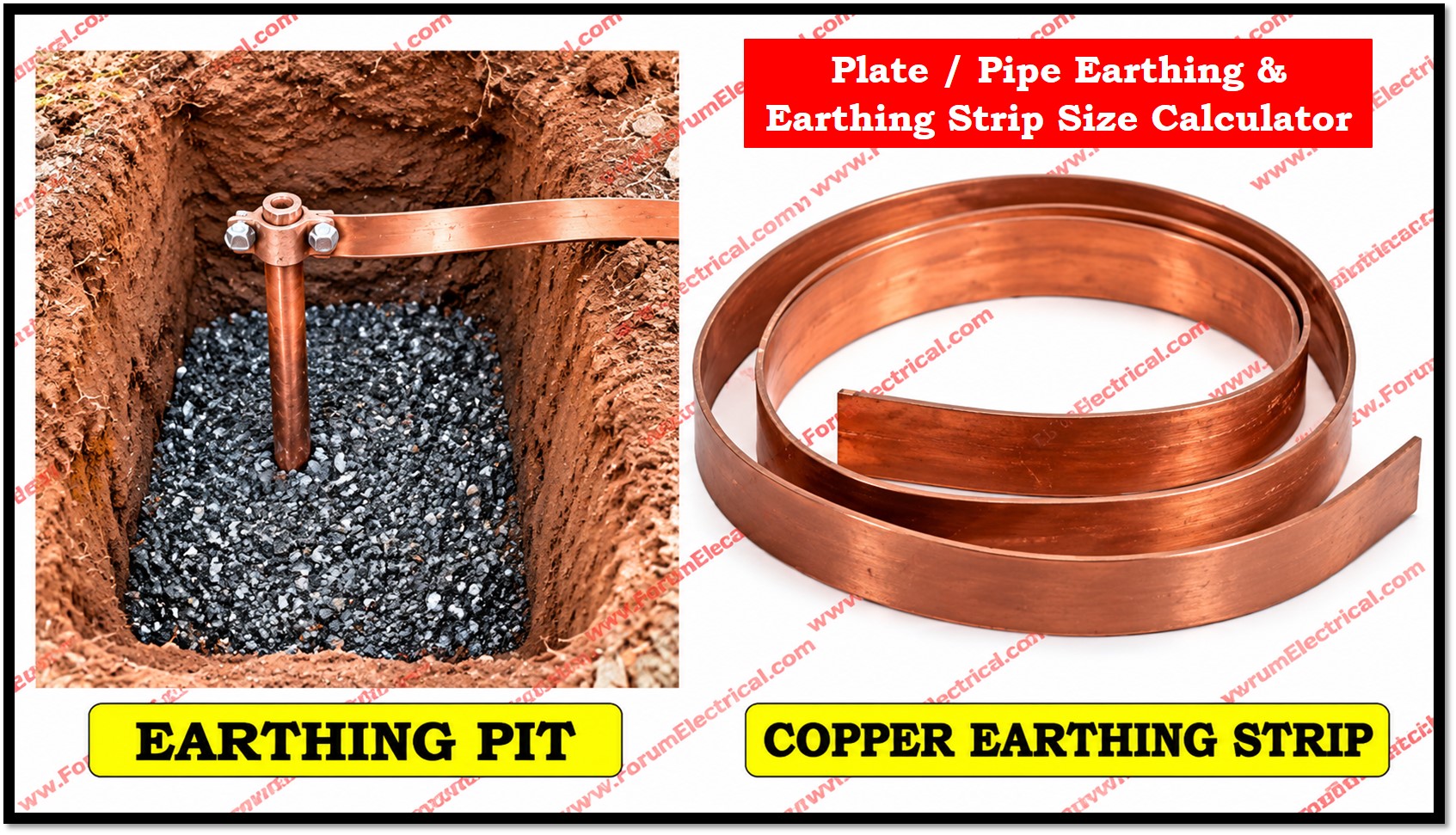
An effective earthing system provides a controlled path for fault current and helps to maintain electrical safety by limiting dangerous potential differences between equipment, structures and general mass of earth.
Calculator
Plate / Pipe Earthing & Earthing Strip Size Calculator
A. Earth Electrode Resistance & Number of Electrodes
The electrode calculation assumes homogeneous soil and uses simplified equations for preliminary estimation. Multiple-electrode resistance is calculated using a simplified straight-line mutual-resistance model.
Electrode Results
Calculation
B. Earthing Strip / Conductor Thermal-Withstand Check
The thermal calculation is independent of the electrode-resistance calculation above.
Enter the RMS fault current that actually flows through the conductor being checked. Current division through parallel metallic paths must be considered where applicable.
Conductor Sizing Results
Calculation
Engineering Limitations & Design Checks
- Soil resistivity: Use representative site measurements and the design/worst-season value.
- Homogeneous soil: The simple electrode equations assume uniform soil resistivity. Multilayer soil may require a different grounding model.
- Plate resistance: The IS 3043 plate equation uses the area of both sides of the plate.
- Pipe/rod resistance: The IS 3043:2018 preliminary vertical pipe/rod equation assumes uniform soil and consistent length/diameter units.
- Multiple electrodes: The group calculation is a simplified straight-line approximation. Actual electrode arrays should be checked using their actual geometry, spacing, depth and soil model.
- Target resistance: The target must be based on the applicable project, utility or design requirement.
- Fault current: Use the current actually flowing through the conductor being checked. Current division must be considered.
- Fault duration: Use the actual protection clearing time applicable to the fault.
- k-factor: k depends on material and the selected initial/final temperature conditions. It is not a universal constant.
- Final conductor temperature: The chosen final temperature must be justified by the applicable standard/design basis and joint limitations.
- Touch and step voltage: Meeting an earth-resistance target alone does not demonstrate touch/step-voltage compliance.
- Ground Potential Rise: Substation/high-energy grounding systems may require GPR, touch-voltage, step-voltage and transferred-potential analysis.
- Mechanical and corrosion design: Thermal cross-section is only one design criterion.
- Site verification: The completed grounding installation should be verified using an appropriate grounding-system measurement method.
Formula Reference
R = (ρ / 4) × √(π / A)
A = 2 × L × W
A is the area of both sides of the plate.
R = ρ / (2πL) × ln(2L / d)
L and d must use consistent units.
Rgroup = R/n + ρ/(πsn²) × Σ[(n−j)/j]
j = 1 to n−1
S = If × √t / k
k = √{ [Qc(β+20)/ρ20] × ln[ (β+θf) / (β+θi) ] }
The k-factor material constants used by the calculated method are: Copper β = 234.5, Qc = 3.45 × 10⁻³ J/(°C·mm³), ρ20 = 17.241 × 10⁻⁶ Ω·mm; Aluminium β = 228, Qc = 2.5 × 10⁻³ J/(°C·mm³), ρ20 = 28.264 × 10⁻⁶ Ω·mm; Steel β = 202, Qc = 3.8 × 10⁻³ J/(°C·mm³), ρ20 = 138 × 10⁻⁶ Ω·mm.
Related Electrical Calculators
Related Electrical Calculators
All Categories
Electrical Converters
Electrical Machines Calculators
Transformer Calculators
Power Systems Calculators
Battery Calculators
Electrical Engineering Excel Calculators
Unit Converters
Earthing design is not limited to selecting an electrode with a low resistance value.
A complete design may also require
- Soil-resistivity investigation,
- Electrode geometrics,
- Conductor sizing,
- Fault-current division,
- Touch- and Step-voltage assessment,
- Ground Potential Rise (GPR),
- Corrosion considerations and verification after installation.
The Plate / Pipe Earthing & Earthing Strip Size Calculator is intended as a preliminary engineering tool.
It performs 2 independent calculations:
- Earth-electrode resistance and preliminary electrode quantity and
- Thermal withstand sizing of an earthing strip (or) conductor.
The calculator uses simplified equations and clearly identifies the limitations of those equations.
Earth Electrode Resistance Calculation
The electrode-resistance calculation starts with soil resistivity represented by ρ in ohm-metres (Ω·m).
Soil resistivity is a site-specific parameter and can vary significantly with moisture, temperature, soil composition, depth and seasonal conditions.
A representative site verification should therefore be used instead of assuming a generic soil-resistivity value.
The Wenner four-point method is commonly used for soil-resistivity measurements.
Plate Electrode Formula
For the preliminary plate-electrode calculation the calculator uses the IS 3043:2018 plate expression:
R = (ρ / 4) × √(π / A)
where
R – Approximate resistance of the plate electrode in ohms (Ω)
ρ – soil resistivity in Ω·m and
A – Area of both sides of the plate.
For a rectangular plate of length L and width W, A = 2LW.
For example, for a 1 m × 1 m plate in soil having a resistivity of 200 Ω·m, the effective area is 2 m².
The calculated single-plate resistance is approximately 62.666 Ω.
This result illustrates why electrode resistance cannot be determined from electrode dimensions alone: soil resistivity has a direct and significant effect.
Pipe or Rod Electrode Formula
For a vertical pipe (or) rod electrode the calculator uses the preliminary expression:
R = ρ / (2πL) × ln(2L / d)
Where
L – Electrode length and
d – Diameter.
The length and diameter should be expressed using consistent units.
The equation assumes homogeneous soil and is intended for preliminary estimation.
Actual resistance can differ when soil is layered when electrodes interact strongly (or) when the installation differs from the assumed model.
Multiple Electrodes and Electrode Spacing
Installing multiple electrodes can reduce the overall grounding resistance but the improvement is not simply obtained by dividing the single electrode resistance by the number of electrodes.
Nearby electrodes influence each other through their mutual resistance.
Consequently, electrode spacing, arrangement & soil conditions are important.
The calculator uses a simplified straight-line mutual resistance model for preliminary screening:
Rgroup = R/n + ρ/(πsn²) × Σ[(n−j)/j], j = 1 to n−1
Here
R – Single-electrode resistance
n – Number of electrodes and
s – Center-to-center spacing.
This model is explicitly not presented as a detailed grounding-grid solution.
A final grounding system must be evaluated using the actual electrode layout, burial depth, conductor interconnections and soil model.
Automatic Electrode Quantity
The calculator allows the user to enter zero for the electrode quantity.
In this mode, the program searches from one electrode upward & stops at the first quantity that satisfies the entered target resistance subject to the 500-electrode search limit.
For Example:
With ρ = 200 Ω·m, a 1 m × 1 m plate and 3 m spacing, the simplified model gives approximately 10.360 Ω for ten electrodes and 9.594 Ω for eleven electrodes.
Therefore, when the target is 10 Ω, the preliminary minimum is eleven electrodes under this simplified model.
This automatic result should not be interpreted as a final installation quantity.
The actual number may change after considering soil stratification, electrode depth, conductor layout, mutual coupling & touch- and step-voltage requirements.
Earthing Strip Thermal-Withstand Calculation
The calculator checks the minimum conductor cross-sectional area required by an adiabatic thermal calculation.
The fundamental relationship is:
S = If × √t / k
Where
S – Conductor cross-sectional area in mm²
(If is the RMS fault current flowing through the conductor in amperes)
t – Fault duration in seconds and
k – Material/application-dependent factor in A·√s/mm².
The fault current entered into the calculator must be the current actually flowing through the conductor being checked.
In a substation (or) grid, fault current can divide between parallel earth conductors, cable screens, structures & other metallic paths.
Therefore, using the total fault current without evaluating current division can generate an inappropriate conductor size.
k-Factor & Material Temperature Calculation
When the calculated k-factor method is selected, the calculator uses the IEC 60364-5-54 Annex A relationship:
k = √{ [Qc(β+20)/ρ20] × ln[(β+θf)/(β+θi)] }
The calculation uses material constants for copper, aluminium and steel, together with the selected initial and final temperatures.
The mathematical result is dependent on those inputs.
A calculated k-factor must not be treated as universally applicable to every earthing conductor (or) installation.
Formula Summary
| Calculation | Formula |
| Plate electrode | R = (ρ / 4) x √(π / A), A = 2LW |
| Pipe / rod electrode | R = ρ / (2πL) x ln(2L / d) |
| Simplified group model | Rgroup = R/n + ρ/(πsn²) x Σ[(n−j)/j] |
| Thermal withstand | S = If x √t / k |
| Calculated k-factor | k = √{[Qc(β+20)/ρ20] x ln[(β+θf)/(β+θi)]} |
Engineering Limitations
The calculator should be used as a preliminary engineering aid rather than a replacement for a complete grounding-system study.
Important limitations and checks include:
- Use measured and representative soil resistivity, including appropriate design or seasonal considerations.
- The simple equations assume homogeneous soil; multilayer or complex soil may require a dedicated grounding analysis.
- Verify plate dimensions, material, thickness and burial depth against the applicable standard and project requirements.
- Evaluate actual electrode spacing and geometry because mutual effects can materially influence resistance.
- Confirm the specified target resistance from the project, utility or applicable design requirement; there is no universal target for every installation.
- Use the fault current component actually flowing through the conductor and account for current division.
- Use the actual protection clearing time for the applicable fault condition.
- Check touch voltage, step voltage, GPR and transferred potential where applicable, particularly for substations and high-energy installations.
- Verify mechanical, corrosion and connection requirements in addition to thermal withstand.
- Perform suitable field measurements after installation to verify the completed grounding system.
Conclusion
The Plate / Pipe Earthing & Earthing Strip Size Calculator organizes earthing calculations. It shows how many electrodes and distance affect electrode resistance, whereas the plate & rod equations estimate individual resistance. The thermal section calculates adiabatic screening for an earthing strip (or) conductor using fault current, clearing time and k-factor.
The calculator gives a quick and transparent estimate of how many electrodes are required to approach a target resistance and how large an earthing strip should be to survive a fault thermally.

