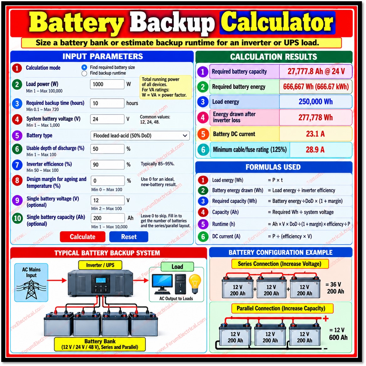
Battery Backup Calculator explains how a battery backup calculator works, the formulas behind it, the inputs it required and the design margins that make its results reliable in practice.
Calculator
Related Electrical Calculators
Related Electrical Calculators
All Categories
Electrical Converters
Electrical Machines Calculators
Transformer Calculators
Power Systems Calculators
Battery Calculators
Electrical Engineering Excel Calculators
Unit Converters
Purpose
The calculator performs an energy balance for inverter (or) UPS systems.
It works in two modes: “Find required battery size” and “Find backup runtime”.
Both use the same chain of factors:
- Inverter efficiency,
- Usable Depth of Discharge (DoD) and
- Design margin.
Inputs and Permitted Ranges
Every input is a text field with a decimal keyboard.
The label of each field displays its allowed range in brackets.
Load, time, bank capacity and single battery capacity start at 0 while the engineering parameters keep standard defaults because 0 is not valid for them.
| Parameter | Unit | Min | Max | Default |
|---|---|---|---|---|
| Load power | W | 1 | 100,000 | 0 |
| Backup time | h | 0.1 | 720 | 0 |
| Bank capacity | Ah | 1 | 100,000 | 0 |
| System voltage | V | 1 | 1,000 | 12 |
| Depth of discharge | % | 1 | 100 | 50 |
| Inverter efficiency | % | 50 | 100 | 90 |
| Design margin | % | 0 | 100 | 20 |
| Single battery voltage | V | 2 | 100 | 12 |
| Single battery capacity | Ah | 1 | 10,000 | 0 (skipped) |
The battery type selector sets the DoD automatically: flooded lead-acid 50%, AGM/Gel 50%, LiFePO4 80%.
Editing the DoD manually switches the selector to “Custom”.
Formulas
Let P be load power, η efficiency as a fraction, d DoD as a fraction, k = 1 + margin ÷ 100 and V the system voltage.
Size Mode
Load energy = P x t
Battery energy drawn = Load energy ÷ η
Required energy = Battery energy ÷ d x k
Required capacity (Ah) = Required energy ÷ V
Runtime Mode
Usable energy = Ah x V x d ÷ k
Runtime (h) = Usable energy x η ÷ P
Both Modes also calculate the DC current and the cable/fuse guideline:
I = P ÷ (η x V) Rating = 1.25 x I
Runtime mode additionally reports the C-rate which is calculated as I ÷ Ah.
If it exceeds 0.5C the tool displays a warning that real lead acid capacity falls at high currents.
Battery Layout
If a single-battery capacity above zero is entered in size mode, the calculator determines the layout.
Batteries in series equal system voltage ÷ single battery voltage which should be a whole number.
Batteries in parallel equal the required Ah ÷ single battery Ah, rounded up.
Total batteries are series x parallel and installed capacity equals parallel strings x single battery Ah at the system voltage.
Battery Chemistry Parameters
| Battery type | Typical usable DoD | Typical cycle life | Peukert exponent |
|---|---|---|---|
| Flooded lead-acid | 50% | 300–1,200 | 1.2–1.3 |
| AGM / Gel lead-acid | 50% | 400–1,000 | 1.1–1.2 |
| LiFePO4 (lithium) | 80–90% | 2,000–6,000 | ≈1.0–1.05 |
Depth of discharge (DoD) limits protect battery life.
Discharging lead-acid batteries deeper than about 50% on a regular basis shortens their service life considerably while lithium iron phosphate tolerates deeper cycling.
Peukert Effect
Lead-acid capacity is not constant; it falls as discharge current rises. Peukert’s law models this:
t = H x (C ÷ (I x H))^k
Here
t – Actual runtime in hours
H – Rated discharge time (commonly 20 h)
C – Capacity rated at that time
I – Discharge current and
K – Peukert exponent.
A 100 Ah battery rated at 20 h (5 A) delivers less than 100 Ah when drawn at 20 A.
Lithium batteries show very small Peukert loss.
Solved Examples
Size mode: 500 W for 4 h, 12 V, 90% efficiency, 50% DoD, 20% margin and 100 Ah batteries gives:
- Load energy 2000 Wh and battery energy drawn 2222 Wh.
- Required energy 5333 Wh (5.33 kWh), equal to 444.4 Ah at 12 V.
- DC current 46.3 A and a 57.9 A cable/fuse guideline.
- Five batteries (1 in series x 5 in parallel) giving 500 Ah installed.
Runtime mode: 500 W, 200 Ah, 12 V, 50% DoD, 20% margin and 90% efficiency gives 1000 Wh usable energy, a runtime of 1.8 h (1 h 48 min), 46.3 A current & a 0.23C discharge rate.
Validation and Error Handling
Each value should be a plain number such as 1500 or 0.5.
Values outside the stated range produce a message naming the allowed limits and the faulty fields receive a red border.
Messages appear in an alert region and the results panel returns to zero values.
The optional single-battery capacity is skipped when blank (or) zero.
A 24 V system built from 12 V units is valid, but a non-multiple such as 12 V from 24 V units is rejected.
Results
Results appear in a stacked list.
Capacity is rounded to one decimal, energy to whole watt-hours, kWh to two decimals, runtime to two decimals and current to one decimal.
Before calculation and after Reset all results show zero.
Interpreting the Results
The headline figure is the required capacity or the estimated runtime.
The design margin raises the required capacity in size mode and lowers the usable energy in runtime mode, so a margin of 0 gives the ideal new-battery result.
Because lithium allows a higher DoD than lead-acid, the same load needs less nominal capacity: with the defaults above, 4444 Wh versus 2778 Wh before margin.
The DC current should be compared with the battery’s maximum continuous discharge rating and the C-rate indicates how hard the bank is working.
Verification
The logic was exercised in a simulated browser environment: the zero start state, error messages, both modes, the series/parallel layout & Reset all behaved as described.
The formulas were checked by hand against the worked examples above.
Limitations
The results are engineering estimates.
The tool assumes a constant power load and nominal battery voltage, whereas real current rises as voltage falls.
It ignores the Peukert effect, temperature curves, motor surge currents, inverter standby consumption, charging time & wiring losses.
The 125% cable/fuse figure is a guideline for continuous loads; final selection should follow the applicable electrical code and manufacturer data.
DoD values are typical and not guaranteed.
Conclusion
Battery backup sizing reduces to a short chain of calculations: load energy, inverter loss, depth of discharge (DoD) and system voltage.
Applying correction factors for ageing, temperature, surge and Peukert losses turns a theoretical figure into a dependable design.
Following these steps ensures that a backup system delivers the required runtime & a long service life.

